
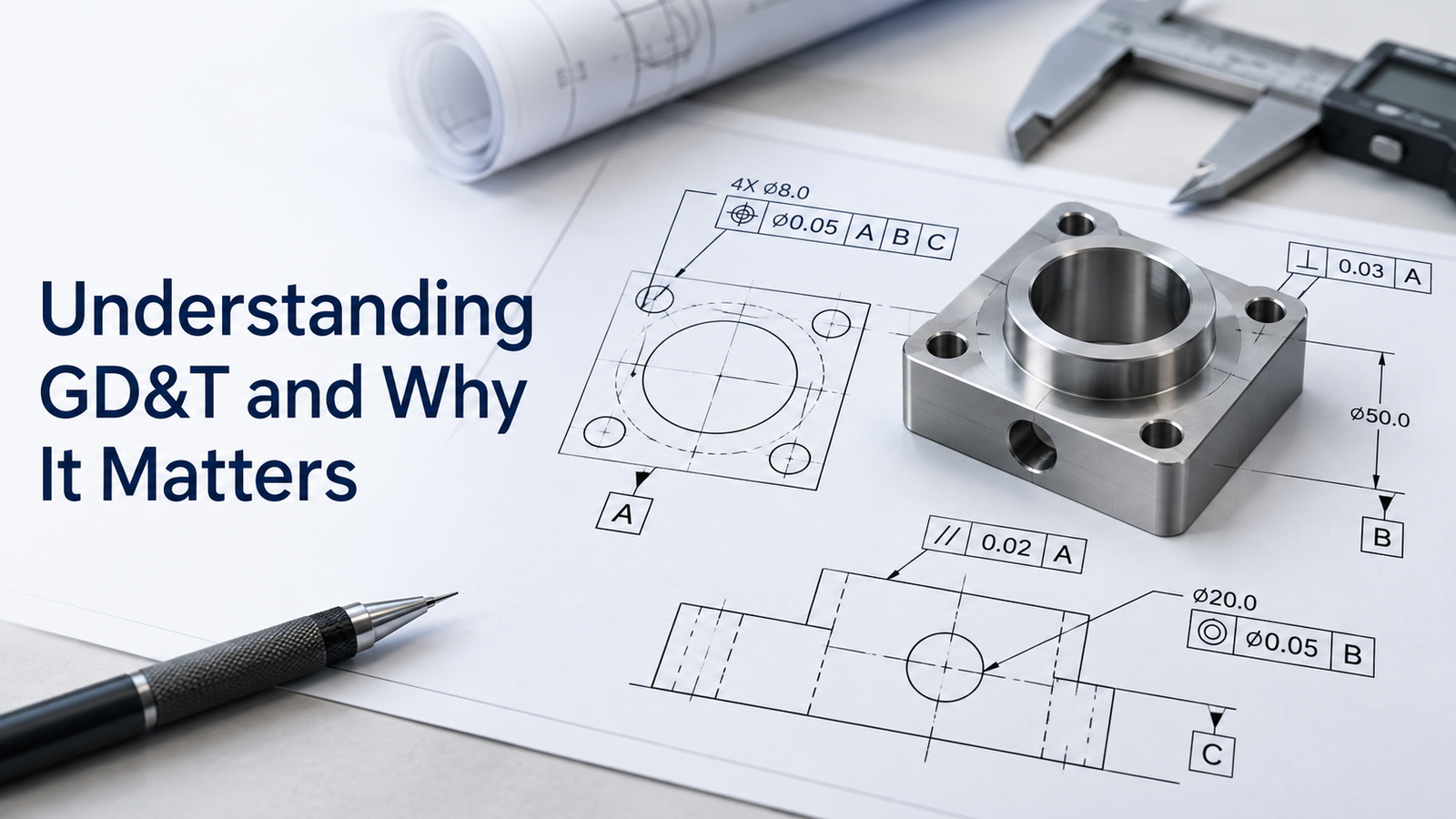
Geometric Dimensioning and Tolerancing, commonly called GD&T, is a standardized engineering language used to control the geometry of manufactured parts.
Traditional dimensions tell us how large a feature should be and where it is located. GD&T goes further by controlling how a feature's form, orientation, location, and runout relate to the functional needs of the design.
This makes geometric dimensioning and tolerancing especially important in mechanical design, manufacturing, inspection, assembly, and quality control.
A shaft may have the correct diameter but still create problems if it is bent. A bearing housing may have the correct bore size but fail if the bore is misaligned. A hole pattern may meet separate X and Y dimensions but still assemble poorly if its true location is not controlled functionally.
GD&T helps engineers describe these conditions more clearly.
ISO 1101:2017 remains the current published ISO standard for geometrical tolerancing, while ASME Y14.5-2018, reaffirmed in 2024, remains in effect and is widely used for dimensioning and tolerancing.
This guide explains the fundamentals of GD&T, the main concepts engineers need to understand, and why it matters in real design and manufacturing work.
Key Steps and Considerations
1. What Is GD&T?
GD&T is a symbolic language used on engineering drawings and digital product definitions to specify allowable geometric variation.
It can control characteristics such as:
- Flatness
- Straightness
- Parallelism
- Perpendicularity
- Position
- Profile
- Runout
ISO 1101 defines the ISO symbol language for geometrical specification and the rules for interpreting those specifications.
ASME Y14.5 similarly establishes symbols, rules, definitions, requirements, defaults, and recommended practices for applying GD&T to engineering drawings and digital models.
The purpose is not simply to make parts more precise.
The purpose is to communicate design intent clearly.
2. Why GD&T Is Needed
A part can meet all simple size dimensions and still fail to work correctly.
For example:
- A mounting face may be warped.
- A shaft axis may be tilted.
- A bolt-hole pattern may be shifted.
- A rotating surface may have excessive runout.
Basic plus/minus tolerancing does not always describe these geometric conditions efficiently.
GD&T helps control the geometry that affects function.
This improves:
- Fit
- Assembly
- Alignment
- Interchangeability
- Inspection
- Performance
ASME describes GD&T as an essential tool for communicating form, fit, function, and interchangeability while reducing manufacturing guesswork.
3. What Is a Feature?
A feature is a physical portion of a part.
Examples include:
- Surface
- Hole
- Slot
- Pin
- Shaft
- Plane
A GD&T control is applied to a feature or derived feature depending on the requirement.
Understanding exactly which feature is controlled is important because the same symbol can have different implications depending on what it is applied to.
4. What Is a Datum?
A datum is a theoretically exact reference used to establish the orientation or location of other features.
A datum feature is the actual physical feature on the part used to establish that reference.
Common datum features include:
- Flat mounting surfaces
- Bearing bores
- Shaft diameters
- Locating holes
Datums create a consistent coordinate framework for:
- Manufacturing
- Inspection
- Assembly
A good datum system should reflect how the part actually functions.
5. What Is a Datum Reference Frame?
A datum reference frame is the coordinate system created by the specified datum sequence.
For example:
A | B | C
normally represents primary, secondary, and tertiary datum references.
The sequence matters.
The primary datum usually establishes the main orientation.
The secondary datum constrains additional degrees of freedom.
The tertiary datum completes the location.
A good datum reference frame helps ensure that manufacturing and inspection evaluate the part in the same functional orientation.
6. What Is a Feature Control Frame?
A feature control frame is the rectangular box that contains the GD&T requirement.
It may include:
- Geometric characteristic symbol
- Tolerance value
- Diameter symbol
- Material-condition modifier
- Datum references
For example, a position tolerance may identify:
- The allowed positional variation
- Whether the tolerance zone is cylindrical
- Whether MMC applies
- Which datums control the feature
The feature control frame is one of the most important pieces of GD&T notation.
7. What Are Basic Dimensions?
Basic dimensions define theoretically exact values.
They are commonly used with geometric tolerances such as:
- Position
- Profile
Instead of giving the feature location a plus/minus tolerance, the basic dimension defines the exact nominal location and the feature control frame defines the permitted geometric variation.
This separates design intent from allowable deviation.
8. Form Controls
Form controls describe the shape of a feature itself.
Common form controls include:
- Straightness
- Flatness
- Circularity
- Cylindricity
Form tolerances generally do not require datum references because they control the feature independently.
Flatness Example
A mounting surface may need to be sufficiently flat so that:
- A gearbox seats properly
- A linear guide mounts without distortion
- A fixture remains stable
A flatness tolerance controls the entire surface between two parallel planes.
9. Orientation Controls
Orientation controls specify how a feature is oriented relative to a datum.
Common orientation controls include:
- Parallelism
- Perpendicularity
- Angularity
These controls require a datum reference because orientation is relative to another feature.
Perpendicularity Example
A shaft shoulder may need to be perpendicular to the shaft datum axis.
If it is tilted, a bearing may not seat evenly.
A perpendicularity tolerance can control this relationship directly.
10. Location Controls
Location controls define where features are located relative to datums.
The most common example is position.
Position tolerance is widely used for:
- Hole patterns
- Pins
- Bores
- Locating features
It can provide a more functional tolerance zone than separate coordinate tolerances.
This is one of the main reasons GD&T can improve manufacturability and assembly.
11. What Is True Position?
True position is the theoretically exact location of a feature established by basic dimensions.
The position tolerance defines how far the actual feature may deviate from that theoretically exact location.
For a cylindrical hole or pin, the tolerance zone is often cylindrical.
This is useful because many mechanical assemblies depend on radial clearance rather than independent X and Y variation.
12. Profile Controls
Profile tolerances can control:
- Lines
- Surfaces
- Complex shapes
Profile is especially useful for:
- Castings
- Molded parts
- Aerodynamic surfaces
- Complex machined geometry
Depending on the specification and datum references, profile can control:
- Form
- Orientation
- Location
This makes profile one of the most flexible GD&T tools.
13. Runout Controls
Runout is used primarily for rotating components.
Typical applications include:
- Shafts
- Spindles
- Couplings
- Pulleys
- Rotors
Two common runout controls are:
- Circular runout
- Total runout
Circular runout evaluates individual cross-sections as the part rotates around the datum axis.
Total runout evaluates variation across the complete controlled surface.
Runout can help control vibration, seal performance, and rotational accuracy.
14. What Is Maximum Material Condition?
Maximum Material Condition, or MMC, describes the condition where a feature contains the greatest amount of material.
For an internal feature such as a hole:
MMC = smallest permitted hole size
For an external feature such as a pin:
MMC = largest permitted pin size
MMC is often used with position tolerances.
It can provide bonus geometric tolerance when the actual feature departs from MMC while still protecting worst-case assembly.
15. What Is Least Material Condition?
Least Material Condition, or LMC, is the opposite of MMC.
For a hole:
LMC = largest permitted hole size
For a pin:
LMC = smallest permitted pin size
LMC can be useful where minimum remaining material is important.
Examples include:
- Minimum wall thickness
- Edge distance
- Structural material around a hole
16. What Is Regardless of Feature Size?
When a material-condition modifier is not applied under ASME practice, a geometric tolerance commonly applies regardless of the actual feature size.
This means the specified geometric tolerance does not increase simply because the feature departs from MMC.
Engineers should understand the governing standard because default rules differ in detail between standards systems.
17. What Is Bonus Tolerance?
Bonus tolerance can occur when a feature controlled at MMC departs from its maximum-material size.
For example, if a hole is larger than its MMC size, additional positional variation may be permitted while still maintaining the worst-case assembly boundary.
This can improve manufacturability.
However, engineers should use MMC only when it reflects the actual functional relationship.
18. Tolerance Zones Matter
GD&T defines tolerance zones geometrically.
Examples include:
- Two parallel planes
- Cylindrical zones
- Surface boundaries
The tolerance-zone shape is important because it determines how actual part variation is evaluated.
A position tolerance on a cylindrical feature often creates a cylindrical zone, which can represent assembly function more efficiently than rectangular coordinate limits.
19. GD&T and Interchangeability
Interchangeability means that one conforming part can replace another without custom fitting.
GD&T supports interchangeability by defining the geometric conditions that parts must satisfy.
This is important in:
- Mass production
- Spare parts
- Supplier changes
- Maintenance
Good GD&T reduces dependence on manual adjustment.
20. GD&T and Inspection
GD&T provides measurable acceptance criteria.
Inspection methods may include:
- Surface plates
- Dial indicators
- Functional gauges
- Coordinate Measuring Machines
A well-designed tolerance scheme should be inspectable.
NIST notes that GD&T is used in engineering product definition and that it supports dimensional metrology and downstream conformance assessment.
Inspection planning should therefore be considered when the tolerance is created.
21. GD&T and Manufacturing
Manufacturing teams use GD&T to understand what geometry is truly critical.
For example:
- Position may control a hole pattern.
- Flatness may control a mounting face.
- Runout may control a shaft surface.
This can help manufacturers choose the appropriate:
- Setup
- Fixture
- Process
- Inspection method
Clear requirements reduce guesswork.
22. GD&T and Mechanical Design
GD&T should follow the function of the part.
A designer should first ask:
- What surfaces locate the part?
- Which features must align?
- Which dimensions affect assembly?
- Which surfaces rotate?
- Which errors would cause failure?
Then select the GD&T controls that protect those relationships.
The goal is not to add as many symbols as possible.
The goal is to define the geometry required for reliable function.
GD&T Fundamentals at a Glance
| GD&T Concept | Purpose |
|---|---|
| Datum | Functional reference |
| Feature control frame | Defines geometric requirement |
| Basic dimension | Exact nominal geometry |
| Flatness | Controls surface form |
| Parallelism | Controls orientation |
| Perpendicularity | Controls 90-degree relationship |
| Position | Controls feature location |
| Profile | Controls lines or surfaces |
| Runout | Controls rotating geometry |
| MMC | Protects worst-case material boundary |
| LMC | Protects minimum material |
| Bonus tolerance | Adds allowable variation under MMC |
Common Beginner GD&T Mistakes
Avoid these mistakes:
- Choosing datums unrelated to function
- Adding GD&T without a clear reason
- Applying very tight tolerances everywhere
- Confusing size tolerance with geometric tolerance
- Forgetting basic dimensions
- Misunderstanding MMC and LMC
- Using flatness when orientation control is required
- Using runout without establishing the correct datum axis
- Mixing ISO and ASME conventions without identifying the governing standard
Good GD&T should make design intent clearer, not more confusing.
ISO vs ASME GD&T
Two major frameworks are widely used:
- ISO GPS / ISO 1101
- ASME Y14.5
They share many concepts but are not identical in every rule, default, and interpretation.
ISO 1101:2017 remains current and provides the foundation for geometrical specification under ISO.
ASME Y14.5-2018 (R2024) remains in effect and is widely used in North American industry.
Engineering organizations should clearly define which standard governs their drawing or digital model.
Why GD&T Matters More in Modern Digital Engineering
GD&T is increasingly embedded directly in 3D CAD models as Product Manufacturing Information.
NIST has highlighted the reuse of digital GD&T information across:
- Engineering
- Production
- Inspection
This makes correct tolerancing even more important.
A poorly defined tolerance can now propagate automatically through multiple digital systems.
GD&T knowledge therefore remains essential even as companies move toward Model-Based Definition and drawingless workflows.
Conclusion
Geometric dimensioning and tolerancing is a practical engineering language for controlling the geometry that matters to product function.
It helps designers define form, orientation, location, and runout more effectively than basic plus/minus dimensions alone.
Datums establish functional references. Feature control frames define geometric requirements. Basic dimensions define exact nominal geometry. MMC and LMC can connect feature size to tolerance behavior. Position, profile, flatness, perpendicularity, and runout help control important mechanical relationships.
ISO 1101:2017 remains the current ISO foundation for geometrical tolerancing, while ASME Y14.5-2018 (R2024) remains in effect and is widely used for design, manufacturing, and inspection.
The biggest benefit of GD&T is not greater complexity.
It is clearer design intent.
When used correctly, GD&T can improve fit, assembly, interchangeability, inspection, manufacturing consistency, and overall mechanical performance.