
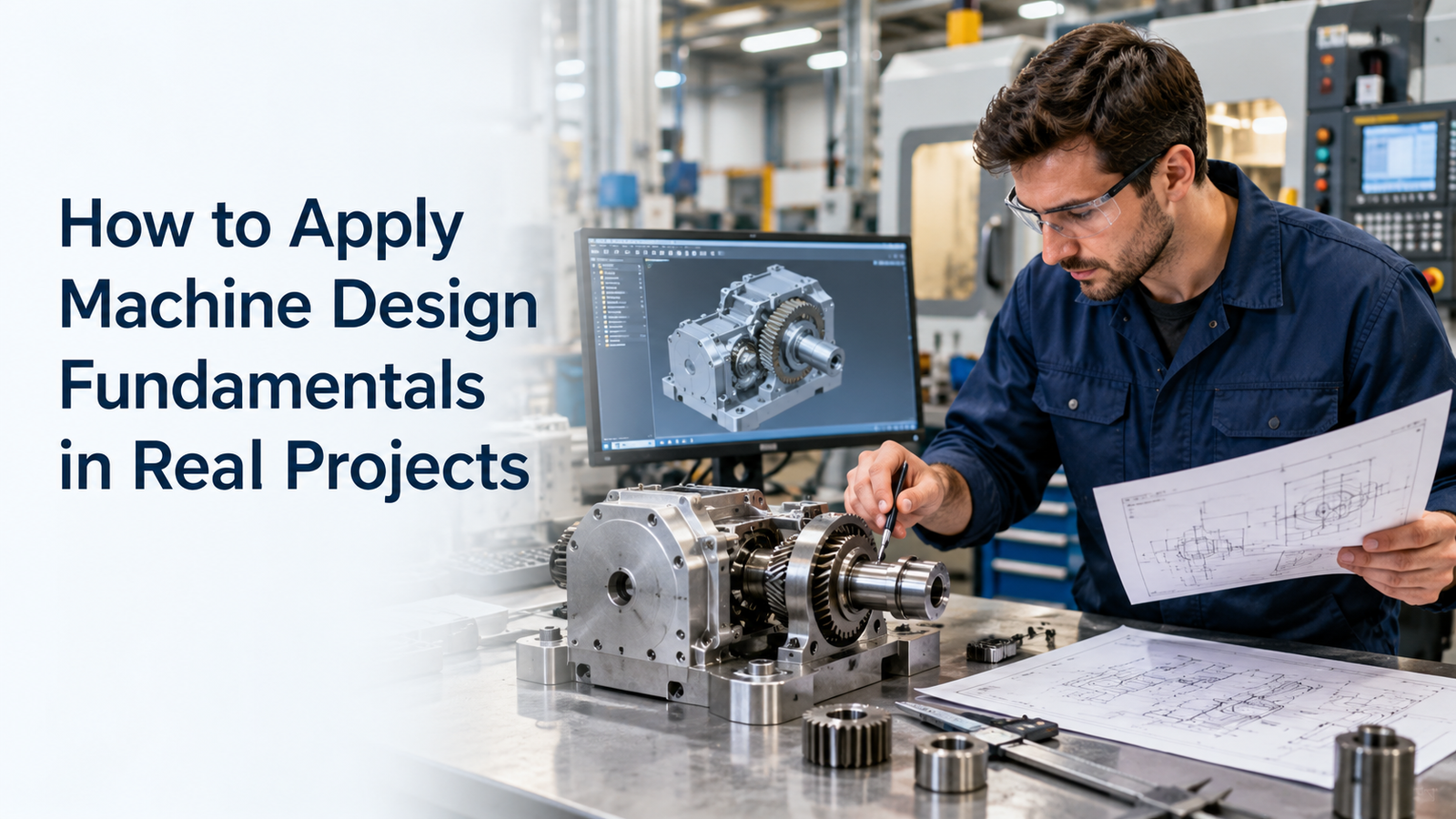
Understanding machine design theory is important, but real engineering begins when those fundamentals are applied to an actual machine.
A real project requires engineers to convert an idea into a working system that is strong enough, accurate enough, safe enough, easy to manufacture, and practical to maintain. This means combining load calculations, motion analysis, component selection, CAD design, tolerances, materials, assembly planning, safety, testing, and documentation.
Good machine design fundamentals installation practices help engineers avoid common project problems such as undersized components, excessive deflection, poor alignment, difficult assembly, unsafe motion, unexpected vibration, and expensive redesign.
This guide explains a practical step-by-step workflow for applying machine design fundamentals in real industrial projects.
Implementation Steps and Best Practices
1. Start With a Clear Requirement
Every machine-design project should begin with a written requirement.
Define:
- What the machine must do
- Product or workpiece size
- Required cycle time
- Load
- Travel distance
- Speed
- Acceleration
- Accuracy
- Repeatability
- Available installation space
- Operating environment
- Safety requirements
- Maintenance expectations
For example, suppose a project requires a positioning table to move a 40 kg fixture through 800 mm in two seconds with repeatable positioning.
That requirement immediately affects the choice of:
- Linear guides
- Actuator
- Motor
- Frame
- Bearings
- Coupling
- Sensors
Without measurable requirements, component selection becomes guesswork.
2. Convert Requirements Into Engineering Values
The next step is to turn the functional requirement into calculations.
Important engineering values may include:
- Force
- Torque
- Speed
- Acceleration
- Inertia
- Bending moment
- Deflection
- Power
- Service life
For linear motion:
Force = Mass × Acceleration
For rotary systems, torque must consider load inertia, acceleration, friction, and transmission efficiency.
THK's linear-guide selection guidance, for example, considers mass, load direction, center of gravity, speed, acceleration, duty cycle, stroke, and required service life when calculating applied load. citeturn120983search6
This is why real design work should begin with operating conditions rather than catalog dimensions.
3. Create More Than One Concept
Do not immediately design the first idea in detail.
Create two or three possible concepts.
For example, a linear positioning mechanism might use:
- Ball screw
- Timing belt
- Pneumatic cylinder
- Electric actuator
Compare each concept for:
- Speed
- Accuracy
- Cost
- Maintenance
- Load capacity
- Space
- Control complexity
A ball screw may provide better positioning accuracy, while a belt drive may be better for long, fast travel.
Concept comparison early in the project is much cheaper than redesigning after manufacturing.
4. Build a Preliminary Layout
Create a simple layout before detailed CAD modeling.
Place:
- Frame
- Moving carriage
- Motor
- Bearings
- Linear guides
- Actuator
- Sensors
- Guards
- Service access
Check whether components physically fit.
Also consider:
- Cable routing
- Lubrication access
- Fastener access
- Tool clearance
- Maintenance space
A design that looks correct in a component calculation may still be difficult to assemble if fasteners cannot be reached.
5. Calculate Loads Before Selecting Components
Do not select components based only on machine mass.
Real machines experience:
- Static load
- Dynamic load
- Shock
- Moment load
- Acceleration load
- External process forces
For example, an overhung carriage may generate a large moment on a linear guide even when total mass is moderate.
THK's selection flow includes applied load, equivalent load, static safety factor, average load, nominal life, environment, preload, and accuracy. citeturn120983search0
This structured approach is useful for many machine components.
6. Select Linear Guides for Real Operating Conditions
Linear-guide selection should consider:
- Load direction
- Moment load
- Number of blocks
- Mounting orientation
- Speed
- Acceleration
- Required travel life
- Accuracy
- Environment
Do not choose a rail only because its catalog load rating looks high enough.
Guide life depends on repeated loading. THK defines nominal life in terms of travel distance under load before rolling fatigue appears and also requires consideration of temperature, contact conditions, lubrication, and environment. citeturn120983search4turn120983search5
In practice, also confirm:
- Rail mounting surface
- Parallelism
- Lubrication access
- Protection from contamination
7. Select the Drive System
The drive system creates motion.
Common options include:
- Ball screw
- Belt drive
- Rack and pinion
- Pneumatic cylinder
- Hydraulic actuator
Selection depends on:
- Required force
- Travel
- Speed
- Accuracy
- Duty cycle
- Environment
- Budget
For high-accuracy positioning, a ball screw may be suitable.
For long travel at high speed, a belt or rack-and-pinion system may be more practical.
The drive should be selected as part of the complete motion system rather than as an isolated component.
8. Select the Motor After Calculating the Motion
Motor selection should be based on actual torque and speed requirements.
Check:
- Continuous torque
- Peak torque
- Maximum speed
- Acceleration torque
- Load inertia
- Gear ratio
- Duty cycle
A motor that provides enough steady-state power may still be unable to accelerate the load fast enough.
This is especially important in:
- Servo axes
- Indexing machines
- Pick-and-place systems
- High-speed automation
Do not oversize excessively either, because a larger motor increases cost and inertia.
9. Design the Frame for Rigidity
Machine frames must be strong, but they must also be stiff.
A frame that does not fail structurally may still deflect enough to reduce accuracy.
Check:
- Bending
- Torsion
- Joint stiffness
- Support locations
- Mounting surfaces
For precision machines, small deflections can affect alignment between guides, shafts, tools, and sensors.
Use suitable structural members and place loads close to supports where practical.
10. Apply Tolerances Carefully
Not every dimension requires a tight tolerance.
Tight tolerances increase:
- Machining cost
- Inspection effort
- Assembly difficulty
Apply tighter tolerances only where function requires them.
Examples include:
- Bearing fits
- Guide mounting surfaces
- Shaft diameters
- Locating features
- Precision interfaces
Other dimensions may use general fabrication tolerances.
THK defines linear-guide accuracy in terms such as running parallelism and dimensional variation, showing why mounting-surface quality directly affects motion accuracy. citeturn120983search2
11. Design for Assembly
Good machine design considers how technicians will assemble the machine.
Ask:
- Can bolts be tightened?
- Can bearings be installed?
- Can rails be aligned?
- Can the motor be removed?
- Is there space for tools?
- Can cables be routed?
Avoid designs that require major disassembly to replace a simple component.
Use locating features such as:
- Dowels
- Shoulders
- Reference surfaces
These help make assembly repeatable.
12. Design for Maintenance
Maintenance requirements should influence design before fabrication.
Consider access to:
- Lubrication points
- Bearings
- Sensors
- Motors
- Belts
- Couplings
- Filters
- Fasteners
THK notes that lubrication and environmental protection have a major effect on linear-guide wear and service life. citeturn120983search5
A component that is difficult to lubricate or replace may create unnecessary downtime.
13. Include Safety During Design
Safety should be built into the machine, not added only after assembly.
ISO 12100 provides a framework for machinery risk assessment and risk reduction.
During design, consider:
- Pinch points
- Rotating parts
- Crushing zones
- Stored energy
- Falling loads
- Sharp edges
- Hot surfaces
- Unexpected motion
Possible risk-reduction measures include:
- Guards
- Covers
- Mechanical stops
- Safe access
- Braking
- Proper structural design
Safety review should begin while the design is still easy to modify.
14. Create Detailed CAD and Drawings
After calculations and concept approval, create the detailed design.
The CAD model should include:
- Production parts
- Purchased components
- Fasteners
- Sensors
- Guards
- Cables where important
Then prepare manufacturing drawings with:
- Dimensions
- Tolerances
- Material
- Surface treatment
- Finish
- Quantity
- Assembly notes
Avoid relying only on the 3D model.
Manufacturing and inspection teams need clear drawings.
15. Review the Design Before Manufacturing
Before releasing drawings, conduct a design review.
Check:
- Loads
- Component capacity
- Interference
- Fastener access
- Assembly sequence
- Safety
- Maintenance
- Sensor locations
- Cable routing
A checklist can prevent small mistakes from reaching manufacturing.
For larger projects, mechanical, electrical, automation, manufacturing, and maintenance teams should review the design together.
16. Prototype Critical Areas When Necessary
Not every project needs a complete prototype.
However, prototype critical mechanisms when there is uncertainty in:
- Motion
- Gripping
- Feeding
- Alignment
- Vibration
- Cycle time
A simple test fixture can identify problems before the final machine is built.
This is particularly useful for new mechanisms without previous application experience.
17. Assemble Using Reference Surfaces
During assembly, use the designed locating surfaces and datums.
For linear systems:
- Clean mounting surfaces
- Check burrs
- Align rails correctly
- Follow tightening sequence
- Check parallelism
Poor installation can reduce the performance of even correctly selected components.
Precision components depend on proper mounting.
18. Test One Function at a Time
Do not immediately run the complete machine at full speed.
Start with:
- Manual movement
- Low-speed operation
- Sensor checks
- Limit checks
- Load testing
- Automatic cycle
- Full-speed testing
Monitor:
- Noise
- Temperature
- Vibration
- Motor load
- Positioning
- Alignment
Gradual commissioning makes faults easier to isolate.
19. Validate Against Original Requirements
Return to the original requirement document.
Verify:
- Cycle time
- Load capacity
- Accuracy
- Repeatability
- Reliability
- Safety
- Maintainability
A machine is successful only if it meets the required function.
Passing individual component checks is not enough.
Real Machine Design Project Workflow
| Project Stage | Main Activity |
|---|---|
| Requirements | Define function and performance |
| Calculations | Load, force, torque and life |
| Concept | Compare design alternatives |
| Layout | Check space and interfaces |
| Selection | Choose components |
| Detailed design | CAD and drawings |
| Safety | Assess hazards |
| Review | Verify design |
| Manufacturing | Produce components |
| Assembly | Install and align |
| Testing | Validate function |
| Commissioning | Run full system |
| Documentation | Record final design |
Common Real-Project Design Mistakes
Avoid these mistakes:
- Starting CAD before defining requirements
- Selecting components before calculating loads
- Ignoring acceleration
- Checking strength but not deflection
- Using unnecessarily tight tolerances
- Forgetting assembly access
- Ignoring maintenance
- Adding safety only at the end
- Testing immediately at full speed
- Failing to compare final performance with requirements
Good machine design is a controlled engineering process, not simply a collection of components.
Conclusion
Applying machine design fundamentals in a real project requires connecting theory with practical engineering decisions.
A good machine design fundamentals installation workflow starts with requirements and calculations, then moves through concept selection, component sizing, CAD, tolerances, assembly planning, safety, testing, and commissioning.
The most successful machines are not simply those with strong components. They are machines where loads, motion, rigidity, accuracy, maintenance, safety, and manufacturing have been considered together.
By using a structured design process, engineers can reduce redesign, avoid component failures, improve machine performance, and create equipment that is easier to manufacture and maintain.