
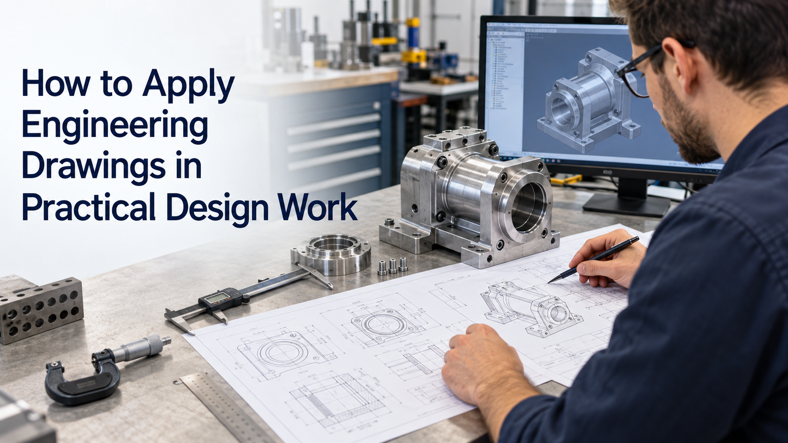
Engineering drawings are one of the most important communication tools in mechanical and industrial design.
A good drawing connects design intent with manufacturing, assembly, inspection, installation, and maintenance. It tells the machinist what to produce, the inspector what to verify, the assembler how parts fit together, and the maintenance team which components and interfaces matter.
This is why understanding engineering drawings installation is important in practical design work.
A 3D CAD model may show what a component looks like, but a production drawing defines the dimensions, tolerances, datums, surface requirements, materials, notes, and revision information needed to manufacture and verify it correctly.
This guide explains how to apply engineering drawings in real projects from the first design concept through manufacturing, assembly, installation, and inspection.
Implementation Steps and Best Practices
1. Start With the Function of the Part
Before creating a drawing, understand what the part must do.
Ask:
- What loads does it carry?
- What components connect to it?
- Which surfaces locate the part?
- Which holes are functional?
- Which dimensions affect alignment?
- Which surfaces require accuracy?
- Which features are noncritical?
This helps distinguish functional dimensions from less important dimensions.
For example, a motor mounting plate may require accurate hole locations and a flat mounting face, while its outer profile may have a much wider tolerance.
Good drawings communicate the functional requirements without over-controlling every dimension.
2. Use Clear Drawing Views
Choose views that describe the geometry clearly.
Common drawing views include:
- Front view
- Top view
- Side view
- Isometric view
- Section view
- Detail view
ISO 128-3:2022 defines general principles for views, sections, and cuts used in technical product documentation.
Use only the views needed to communicate the part.
Too many views can make a drawing crowded.
Too few views can make the geometry ambiguous.
3. Use Section Views for Internal Features
Section views are useful when internal geometry cannot be explained clearly using external views.
Examples include:
- Counterbores
- Internal shoulders
- Bearing seats
- Keyways
- Internal cavities
- Stepped holes
A section view reduces hidden-line clutter and makes important internal dimensions easier to understand.
For assemblies, section views can also help show:
- Bearing arrangement
- Shaft position
- Spacer sequence
- Seal location
- Fastener installation
4. Apply Correct Line Conventions
Different line types communicate different information.
Typical drawing lines include:
- Visible outlines
- Hidden lines
- Centerlines
- Dimension lines
- Extension lines
- Cutting-plane lines
ISO 128-2:2022 defines line types and general draughting rules for technical drawings.
Consistent line conventions help manufacturers and inspectors interpret drawings quickly.
Avoid using decorative line styles that do not follow a recognized technical drawing convention.
5. Dimension From Functional Datums
Dimensions should be related to how the part functions and is assembled.
For example, if a plate is located against one machined edge, use that edge as a primary reference rather than dimensioning critical holes from an unrelated external surface.
Good datum selection improves:
- Manufacturing consistency
- Inspection
- Assembly
- Alignment
Typical functional datum features include:
- Mounting faces
- Locating edges
- Bearing bores
- Shaft axes
- Dowel holes
The drawing should reflect how the component is actually located in the machine.
6. Avoid Unnecessary Chain Dimensioning
Chain dimensioning can create tolerance accumulation.
For example:
- A
- B
- C
- D
If each dimension has a tolerance, the final feature position may accumulate all of those variations.
Where several features must be accurately located from one reference, baseline or datum-based dimensioning may provide better control.
This is especially useful for:
- Hole patterns
- Guide mounting holes
- Bearing supports
- Fixture locations
The dimensioning method should support functional assembly.
7. Apply Tolerances Only Where Needed
Every manufactured dimension varies.
Tolerances define how much variation is acceptable.
ISO 129-1:2018 remains the current published ISO standard for presenting dimensions and associated tolerances, although a replacement edition is currently under development.
Tolerances should reflect the actual functional need.
Tight tolerances increase:
- Machining time
- Inspection effort
- Manufacturing cost
- Rejection risk
Apply tighter tolerances to critical features such as:
- Bearing fits
- Shaft diameters
- Guide mounting surfaces
- Locating pins
- Mating interfaces
Use wider tolerances for noncritical features where appropriate.
8. Understand Fits for Shafts and Holes
Many machine components depend on the correct fit.
Examples include:
- Bearings on shafts
- Bearings in housings
- Bushings
- Dowel pins
- Couplings
- Gears
A fit may need to be:
- Clearance
- Transition
- Interference
The correct fit depends on function, load, assembly, and service requirements.
A bearing seat that is too loose may move during operation.
A fit that is too tight may make assembly difficult or damage the component.
The drawing should clearly specify the required size and tolerance.
9. Use GD&T for Functional Geometry
Geometric Dimensioning and Tolerancing (GD&T) controls geometry more directly than simple plus/minus dimensions.
ISO 1101:2017 defines the ISO symbol language and interpretation rules for geometrical tolerancing.
Typical controls include:
- Flatness
- Straightness
- Parallelism
- Perpendicularity
- Position
- Runout
GD&T is useful when the relationship between features matters.
For example, a motor mounting face may need to be perpendicular to a shaft axis, or a bearing bore may need controlled position relative to another datum.
Use GD&T when it communicates function more clearly than conventional coordinate tolerances.
10. Do Not Add GD&T Without Purpose
More symbols do not automatically make a drawing better.
Unnecessary GD&T can:
- Increase manufacturing cost
- Confuse suppliers
- Increase inspection complexity
Each control should solve a functional requirement.
Before adding a geometric tolerance, ask:
- What problem does this control prevent?
- How will it be measured?
- Is the tolerance achievable?
- Does the assembly actually require it?
A clear, simple drawing is usually better than an unnecessarily complicated drawing.
11. Specify Surface Finish Where It Matters
Some surfaces require controlled finish because they interact with:
- Bearings
- Seals
- Sliding components
- Precision mounting surfaces
Do not apply the same fine finish to every surface.
Unnecessary surface-finish requirements increase machining cost.
Specify finish only where it affects:
- Friction
- Sealing
- Wear
- Accuracy
- Appearance
12. Define Material Clearly
A manufacturing drawing should identify the required material.
Depending on the application, this may include:
- Material grade
- Heat treatment
- Hardness
- Coating
- Surface treatment
Examples include:
- Carbon steel
- Stainless steel
- Aluminum
- Tool steel
- Engineering plastics
Material selection should match the load, environment, wear, corrosion, and manufacturing process.
Avoid vague notes such as “steel” when a specific grade is required.
13. Add Manufacturing Notes Carefully
Notes can communicate requirements that are difficult to show with dimensions.
Examples include:
- Remove burrs
- Break sharp edges
- Apply coating
- Heat treatment
- Mark part number
- Clean before assembly
Keep notes short and specific.
Avoid generic notes that are impossible to inspect or verify.
14. Create Assembly Drawings
Individual part drawings explain manufacturing.
Assembly drawings explain how parts fit together.
Assembly drawings may include:
- Item balloons
- Bill of materials
- Fastener locations
- Component orientation
- Section views
- Assembly notes
These are useful for:
- Production
- Installation
- Service
- Spare-parts identification
An assembly drawing should make the build sequence understandable.
15. Use a Bill of Materials
A Bill of Materials (BOM) connects drawing items to actual components.
Typical BOM information includes:
- Item number
- Part number
- Description
- Quantity
- Material or specification
Purchased components such as:
- Bearings
- Motors
- Sensors
- Couplings
- Fasteners
should be clearly identified.
A structured BOM reduces procurement and assembly errors.
16. Apply Drawings During Installation
Engineering drawings are also important during machine installation.
Installation teams may use drawings to verify:
- Base location
- Mounting-hole position
- Machine orientation
- Equipment clearances
- Utility connections
- Interface dimensions
An installation drawing should show only the information needed for site work.
It may include:
- Overall dimensions
- Foundation points
- Anchor locations
- Service clearances
- Connection locations
This helps avoid site modification after equipment arrives.
17. Check Tolerance Stack-Up Before Release
Individual dimensions may be within tolerance while the final assembly still fails.
This can happen because tolerances accumulate.
Review critical stacks such as:
- Shaft and bearing spacing
- Guide alignment
- Gear center distance
- Assembly clearances
- Sensor gaps
Tolerance stack-up analysis is especially important in assemblies with several mating parts.
18. Design Drawings for Inspection
A good drawing should be inspectable.
Ask:
- Can this dimension be measured?
- Is the datum accessible?
- Does the inspection team have suitable equipment?
- Is the tolerance realistic?
Inspection methods may include:
- Calipers
- Micrometers
- Height gauges
- Dial indicators
- CMM measurement
- Gauges
Avoid specifying controls that are extremely difficult to verify unless they are necessary for function.
19. Control Drawing Revisions
Revision control is essential.
A drawing should clearly show:
- Drawing number
- Revision
- Date
- Change description
- Approval
Without revision control, production may manufacture an obsolete design.
After releasing a change:
- Update the drawing.
- Update the BOM if required.
- Notify affected teams.
- Remove obsolete versions from active use.
This becomes especially important when manufacturing is spread across multiple suppliers or locations.
20. Match the Drawing to the Final CAD Model
The released drawing and CAD model should agree.
Before final release, compare:
- Dimensions
- Hole sizes
- Part number
- Material
- Revision
- BOM
A mismatch between the model and drawing creates uncertainty.
Organizations should also define which source controls production if a conflict is found.
Practical Engineering Drawing Workflow
| Stage | Drawing Activity |
|---|---|
| Requirement | Identify functional features |
| CAD design | Create final geometry |
| Datum planning | Define references |
| Dimensioning | Add functional dimensions |
| Tolerancing | Specify allowable variation |
| GD&T | Control critical geometry |
| Material | Define grade and treatment |
| Assembly | Prepare assembly drawing |
| BOM | List all components |
| Review | Check clarity and completeness |
| Manufacturing | Release controlled drawing |
| Inspection | Verify dimensions and geometry |
| Installation | Confirm machine interfaces |
| Revision | Record approved changes |
Common Engineering Drawing Mistakes
Avoid these mistakes:
- Adding dimensions without considering function
- Using too many views
- Missing internal section views
- Applying tight tolerances everywhere
- Poor datum selection
- Excessive chain dimensioning
- Using unnecessary GD&T
- Missing material specifications
- Incomplete BOM information
- Releasing drawings without revision control
- Creating tolerances that cannot be inspected
- Allowing CAD and released drawings to become inconsistent
Good drawings reduce questions, errors, rework, and installation delays.
Conclusion
Engineering drawings are not simply documentation created after design.
They are a critical part of practical engineering work.
A good engineering drawings installation workflow connects design intent with manufacturing, assembly, inspection, installation, and maintenance.
Clear views, functional dimensions, correct datums, practical tolerances, appropriate GD&T, material specifications, assembly information, BOMs, and revision control all improve communication between engineering and production.
Current technical drawing standards such as ISO 128-1, ISO 128-3, ISO 129-1, and ISO 1101 provide structured conventions for representation, dimensioning, and geometrical tolerancing.
When drawings are created around how a component actually functions and will be manufactured, inspected, and installed, they become one of the most powerful tools for reducing errors and improving product quality.