
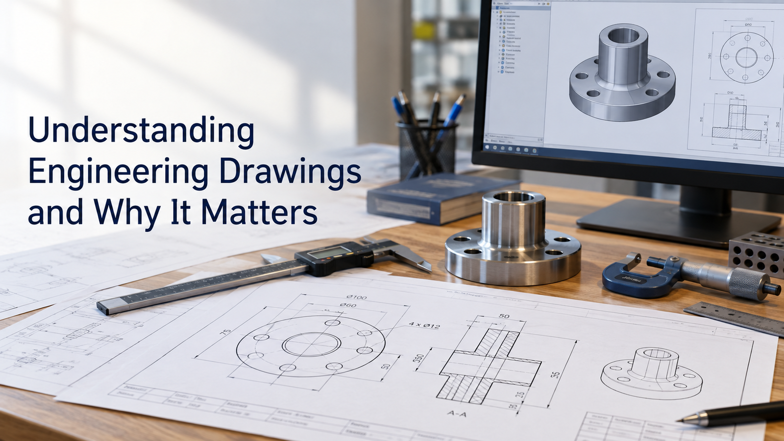
Engineering drawings are one of the most important communication tools in manufacturing, mechanical design, construction, inspection, assembly, and maintenance.
They translate an engineer's design intent into a technical language that manufacturers, inspectors, suppliers, assemblers, and maintenance teams can understand.
A 3D CAD model may show what a part looks like, but engineering drawings explain how the part should be manufactured and verified. They define dimensions, tolerances, materials, fits, surface requirements, geometric relationships, part numbers, and assembly information.
Without clear drawings, even a good design can result in manufacturing errors, poor assembly, incorrect parts, rework, and equipment failures.
This guide explains the fundamentals of engineering drawings, the information they contain, how they are used, and why they remain important in modern engineering.
Key Steps and Considerations
1. What Are Engineering Drawings?
An engineering drawing is a controlled technical document that defines the geometry and requirements of a product or component.
It may describe:
- A single machined part
- A fabricated structure
- A mechanical assembly
- A machine installation
- A complete system
Engineering drawings are designed to remove ambiguity.
A manufacturer should be able to understand:
- What must be made
- What size it must be
- How accurate it must be
- What material should be used
- How it connects to other parts
- How it should be inspected
ISO 128-1:2020 provides general rules for the execution of technical drawings in both 2D and 3D technical product documentation. The standard was reviewed and confirmed in 2026 and remains current.
2. Why Engineering Drawings Matter
Engineering projects involve many different teams.
These may include:
- Design engineering
- Manufacturing
- Procurement
- Quality
- Assembly
- Installation
- Maintenance
Engineering drawings create a common technical reference for these teams.
For example, a drawing can tell:
- A machinist where to drill a hole
- An inspector what tolerance to check
- A purchaser which component to order
- An assembler how parts fit together
- A maintenance technician what replacement dimension is required
This makes drawings an important part of product quality and engineering control.
3. Main Types of Engineering Drawings
Different drawings serve different purposes.
Common types include:
Part Drawings
A part drawing defines a single component.
It may include:
- Dimensions
- Tolerances
- Material
- Surface finish
- Heat treatment
- Notes
Assembly Drawings
An assembly drawing shows how several components fit together.
It may include:
- Item numbers
- Fastener locations
- Component orientation
- Section views
- Bill of Materials
General Arrangement Drawings
General arrangement drawings show the overall machine or system.
They can include:
- Overall dimensions
- Major components
- Interface locations
- Equipment layout
Installation Drawings
Installation drawings help site teams install equipment.
They may show:
- Anchor points
- Foundation dimensions
- Machine orientation
- Utility interfaces
- Service clearances
Each type of drawing communicates a different level of information.
4. Understanding Drawing Views
A three-dimensional object is normally represented using two-dimensional views.
Common views include:
- Front
- Top
- Side
- Isometric
ISO 128-3:2022 specifies general principles for views, sections, and cuts in technical product documentation.
The purpose of multiple views is to describe the geometry clearly.
For a simple plate, one or two views may be enough.
For a complex machined part, several views may be required.
5. What Is Orthographic Projection?
Orthographic projection represents a 3D object using separate 2D views.
Each view shows the object from a different direction.
Typical orthographic views include:
- Front view
- Top view
- Right-side view
These views allow dimensions and features to be communicated without perspective distortion.
Orthographic drawings are widely used because they provide accurate geometric information for manufacturing.
6. Why Section Views Are Used
Some features cannot be shown clearly from external views.
Section views are used to reveal internal geometry.
They may show:
- Bearing seats
- Counterbores
- Internal shoulders
- Keyways
- Internal cavities
- Stepped holes
A section view can reduce the number of hidden lines and make the design easier to understand.
ISO 128-3:2022 covers the general principles for presenting these views and cuts.
7. Understanding Drawing Line Types
Different line types have different meanings.
Common examples include:
- Visible lines
- Hidden lines
- Centerlines
- Dimension lines
- Extension lines
- Cutting-plane lines
Consistent line conventions help users interpret drawings quickly.
For example, a centerline may show the axis of:
- A shaft
- A hole
- A circular feature
Engineering drawings use standardized conventions so that technical information can be understood consistently.
8. Dimensions Define Size and Position
Dimensions define the size or location of features.
Examples include:
- Diameter
- Length
- Thickness
- Hole spacing
- Angle
- Radius
Good dimensioning should define the part completely without unnecessary duplication.
ISO 129-1:2018 remains the current published ISO standard for presenting dimensions and associated tolerances. A replacement edition is under development.
Dimensions should be related to how the component functions and is manufactured.
9. What Are Tolerances?
Manufacturing cannot produce every dimension at exactly one theoretical value.
A tolerance defines the acceptable amount of variation.
For example:
A shaft may have a nominal diameter of 20 mm but be allowed to vary within a small specified range.
Tolerances are important because they control:
- Fit
- Alignment
- Clearance
- Interchangeability
- Performance
Tighter tolerances generally increase manufacturing and inspection cost.
Therefore, engineers should apply precision where it is functionally required.
10. What Are Datums?
A datum is a reference used to locate or orient other features.
Common datum features include:
- Flat mounting surfaces
- Hole axes
- Bearing bores
- Precision edges
Datums are particularly important when features must maintain a controlled relationship.
For example, a hole pattern may need to be located from a mounting face and a locating edge.
Good datum selection improves manufacturing, inspection, and assembly consistency.
11. What Is GD&T?
Geometric Dimensioning and Tolerancing, commonly called GD&T, is a standardized language used to control the geometry of parts.
Common geometric controls include:
- Flatness
- Straightness
- Parallelism
- Perpendicularity
- Position
- Runout
ISO 1101:2017 defines the ISO symbol language for geometrical tolerancing and remains current after its most recent confirmation.
ASME Y14.5-2018 (R2024) is also widely used, particularly in North American engineering and manufacturing.
GD&T helps communicate how features must relate to one another to achieve form, fit, function, and interchangeability.
12. Why Fits Are Important
Many machine components must fit together correctly.
Examples include:
- Shaft and bearing
- Pin and hole
- Bushing and housing
- Coupling and shaft
Fits may be designed as:
- Clearance fit
- Transition fit
- Interference fit
The correct fit depends on the application.
If a fit is too loose, movement or vibration may occur.
If it is too tight, assembly or component performance may be affected.
Drawings communicate the required dimensions and tolerances needed to achieve the intended fit.
13. Material Information on Drawings
Engineering drawings commonly specify the required material.
Examples include:
- Carbon steel
- Stainless steel
- Aluminum
- Tool steel
- Engineering plastic
Depending on the application, drawings may also specify:
- Heat treatment
- Hardness
- Coating
- Plating
- Surface treatment
Material information should be specific enough to ensure the manufactured component has the required properties.
14. Surface Finish Requirements
Surface texture can affect component performance.
It may influence:
- Friction
- Wear
- Sealing
- Bearing seating
- Appearance
Critical surfaces may require a specific finish.
However, specifying a very fine finish on every surface can increase manufacturing cost unnecessarily.
The requirement should match the function.
15. Hole and Thread Callouts
Engineering drawings often contain hole specifications.
A complete callout may identify:
- Hole diameter
- Depth
- Thread size
- Counterbore
- Countersink
- Quantity
Clear hole callouts prevent manufacturing interpretation errors.
Standard thread designations are particularly important for interchangeability.
16. Notes on Engineering Drawings
Some requirements are easier to communicate using notes.
Examples include:
- Remove burrs
- Break sharp edges
- Apply coating
- Heat treat
- Mark part number
Notes should be clear and measurable where possible.
Avoid vague instructions that different suppliers may interpret differently.
17. What Is a Bill of Materials?
A Bill of Materials, or BOM, is commonly used with assembly drawings.
A BOM may contain:
- Item number
- Part number
- Description
- Quantity
- Material
- Supplier information
Item balloons on the drawing connect components to the BOM.
This helps procurement and assembly teams identify the correct parts.
18. Why Revision Control Matters
Engineering designs change.
A drawing may be revised because of:
- Design improvement
- Manufacturing feedback
- Supplier changes
- Safety improvements
- Component replacement
A controlled drawing should normally identify:
- Drawing number
- Revision
- Date
- Change description
- Approval
Without revision control, manufacturing may use an outdated design.
This can create rework, scrap, or assembly problems.
19. How Engineering Drawings Support Manufacturing
Manufacturers use drawings to determine:
- Required dimensions
- Material
- Tolerances
- Hole sizes
- Surface finish
- Special processes
A good drawing reduces the number of questions that must be sent back to engineering.
It also helps suppliers provide more accurate quotations.
20. How Engineering Drawings Support Inspection
Quality inspectors use drawings to determine what must be measured.
They may verify:
- Diameter
- Thickness
- Hole position
- Flatness
- Runout
- Surface condition
A clear drawing establishes acceptance criteria.
ASME notes that standardized dimensioning and tolerancing provides a common language across design, manufacturing, and inspection and helps reduce manufacturing guesswork.
21. How Engineering Drawings Support Assembly
Assembly teams use drawings to understand:
- Component positions
- Orientation
- Fasteners
- Spacers
- Interfaces
Assembly drawings are especially useful for complex mechanisms.
Clear documentation improves build repeatability and reduces the chance of incorrect installation.
22. How Engineering Drawings Support Maintenance
Maintenance teams may use drawings years after a machine is built.
They can help identify:
- Replacement parts
- Bearing fits
- Shaft dimensions
- Assembly arrangements
- Lubrication locations
Accurate as-built drawings become especially important after equipment modifications.
They preserve technical knowledge even when the original design team is no longer available.
Engineering Drawing Fundamentals at a Glance
| Drawing Element | Purpose |
|---|---|
| Views | Show component geometry |
| Sections | Reveal internal features |
| Dimensions | Define size and position |
| Tolerances | Define acceptable variation |
| Datums | Create functional references |
| GD&T | Control geometric relationships |
| Fits | Control mating components |
| Material | Define required material |
| Surface finish | Control functional surfaces |
| Notes | Add manufacturing requirements |
| BOM | Identify assembly components |
| Revision | Control design changes |
Common Beginner Mistakes
New engineers should avoid:
- Missing important dimensions
- Adding duplicate dimensions
- Applying tight tolerances everywhere
- Selecting poor datums
- Using GD&T without understanding the function
- Omitting material specifications
- Forgetting revision control
- Creating drawings that are difficult to inspect
A drawing should be complete but not unnecessarily complicated.
Why Engineering Drawings Still Matter in the Digital Age
Modern engineering increasingly uses:
- 3D CAD
- Model-Based Definition
- Product Manufacturing Information
- Digital threads
- Digital twins
However, the underlying technical concepts remain the same.
Engineers still need to understand:
- Dimensions
- Tolerances
- Datums
- Fits
- GD&T
- Materials
- Design intent
Even when this information is embedded directly into a 3D model, the engineer still needs to define it correctly.
Engineering drawing knowledge therefore remains valuable even as documentation becomes more digital.
Conclusion
Engineering drawings are a fundamental part of engineering communication.
They connect design with manufacturing, inspection, assembly, procurement, installation, and maintenance.
A good drawing clearly defines geometry, dimensions, tolerances, datums, fits, materials, surface requirements, BOM information, and revision status.
Current standards such as ISO 128-1:2020 provide general drawing rules, ISO 128-3:2022 covers views and sections, ISO 129-1:2018 covers presentation of dimensions and tolerances, and ISO 1101:2017 defines the ISO language for geometrical tolerancing.
Understanding these fundamentals helps engineers reduce ambiguity, improve manufacturing quality, control cost, and create products that can be built and maintained consistently.