
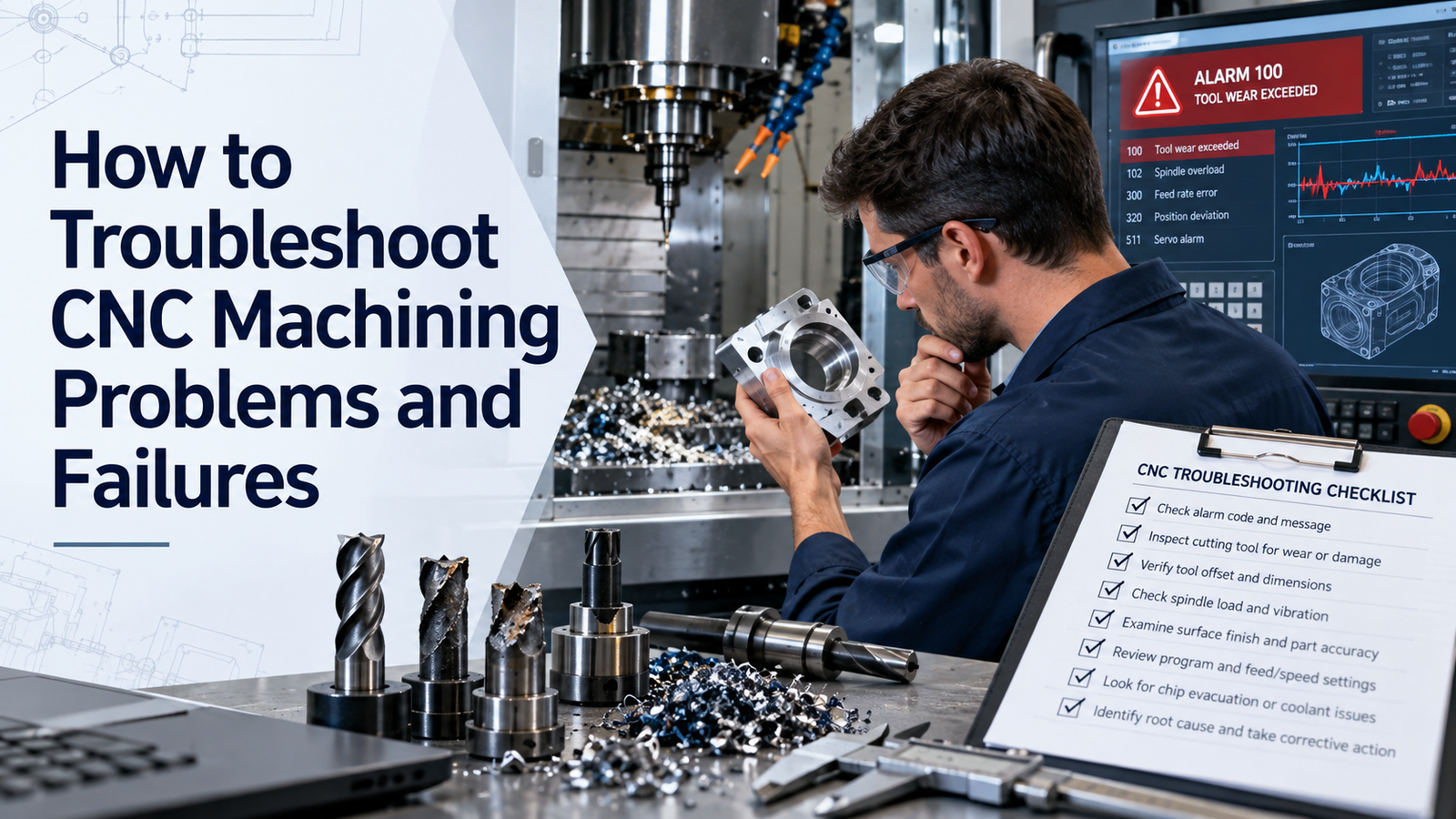
CNC machining problems rarely come from one cause.
Poor surface finish, chatter, broken tools, dimensional variation, burrs, overheating, and tool wear can all result from a combination of cutting data, tool condition, workholding, machine alignment, offsets, coolant delivery, and programming.
Good CNC machining troubleshooting therefore requires a structured approach.
Instead of changing several settings at once, engineers and machinists should identify the symptom, isolate the likely causes, change one variable at a time, and verify the result.
This guide explains how to troubleshoot common CNC machining problems and failures in milling and turning operations.
Key Problems and Solutions
1. Start With the Symptom
Do not begin by changing speeds, feeds, tools, and offsets at the same time.
First identify exactly what is wrong.
Common symptoms include:
- Chatter
- Poor surface finish
- Dimensional error
- Taper
- Excessive tool wear
- Broken cutting tools
- Burrs
- Built-up edge
- Overheating
- Poor chip evacuation
- Spindle vibration
- Workpiece movement
Then determine whether the problem is related mainly to:
- Tooling
- Cutting parameters
- Workholding
- Machine condition
- Program
- Coolant
- Material
A disciplined process prevents random trial-and-error.
2. Troubleshooting Chatter
Chatter is one of the most common CNC machining problems.
It is a self-excited vibration that can create:
- Wavy surface finish
- Noise
- Tool wear
- Reduced accuracy
- Tool breakage
Haas identifies common chatter causes including tool wear, excessive tool length, incorrect chip load, excessive flute engagement, and unstable toolpaths.
Seco also highlights slender tools, weak workholding, high cutting forces, wrong tool geometry, and unsuitable cutting parameters as major contributors to chatter.
How to Fix Chatter
Check:
- Tool wear
- Tool overhang
- Holder rigidity
- Workpiece clamping
- Spindle speed
- Feed rate
- Depth of cut
- Width of cut
Use the shortest practical tool and toolholder.
If possible:
- Reduce tool overhang
- Reduce radial engagement
- Adjust spindle speed
- Increase system rigidity
- Use a constant-engagement toolpath
Do not assume slower feed always reduces chatter. In some cases, an excessively light chip load can make the cut unstable.
3. Poor Surface Finish
Poor surface finish may appear as:
- Chatter marks
- Scratches
- Torn material
- Feed marks
- Steps
Possible causes include:
- Worn tool
- Wrong cutting data
- Tool runout
- Workpiece movement
- Poor machine alignment
- Built-up edge
- Incorrect tool geometry
Haas recommends checking chatter causes, spindle deflection, and machine level when investigating surface-finish problems.
How to Improve Surface Finish
Check:
- Cutting edge condition.
- Tool and holder runout.
- Workholding rigidity.
- Feed and speed.
- Machine alignment.
- Coolant delivery.
Avoid trying to solve every surface problem by simply reducing feed.
The root cause may be vibration, wear, or mechanical instability.
4. Excessive Tool Wear
Tool wear is normal, but rapid or uneven wear indicates a process problem.
Common causes include:
- Cutting speed too high
- Wrong tool grade
- Inadequate coolant
- Excessive cutting force
- Chatter
- Poor chip evacuation
Seco notes that tool-wear patterns such as chipping, built-up edge, and notch wear can often be traced back to stability, speed, feed, coolant, and tool-selection issues.
How to Reduce Tool Wear
Check:
- Tool grade
- Coating
- Cutting speed
- Feed
- Coolant
- Toolpath
- Rigidity
Track tool life instead of waiting for failure.
Predictable tool replacement is usually better than running tools until they break.
5. Tool Chipping
Chipping is the fracture of the cutting edge.
Possible causes include:
- Vibration
- Interrupted cuts
- Incorrect tool geometry
- Excessive feed
- Poor rigidity
- Tool runout
Seco recommends checking setup rigidity, tool length, balance, runout, cutting parameters, tool suitability, and chip evacuation when chipping occurs.
Corrective Actions
- Shorten tool overhang
- Improve workholding
- Check spindle and holder runout
- Adjust cutting data
- Use a tool suited to the material
- Improve chip evacuation
6. Built-Up Edge
Built-up edge occurs when workpiece material adheres to the cutting edge.
It can cause:
- Poor surface finish
- Dimensional variation
- Unstable cutting
Typical causes include:
- Low cutting speed
- High friction
- Inadequate lubrication
- Unsuitable tool geometry
Corrective Actions
Consider:
- Increasing cutting speed
- Improving coolant delivery
- Using a sharper geometry
- Selecting a coating suited to the material
Do not confuse built-up edge with ordinary flank wear.
7. Broken Cutting Tools
A broken tool may result from:
- Excessive feed
- Excessive depth of cut
- Tool wear
- Poor chip evacuation
- Wrong toolpath
- Workholding movement
- Collision
Troubleshooting Steps
Check:
- Was the tool already worn?
- Did chips pack around the cutting edge?
- Did radial engagement increase suddenly?
- Did the workpiece move?
- Did the program create a collision?
Constant-engagement toolpaths can reduce sudden spikes in cutting force during milling.
8. Dimensional Errors
A CNC program may be correct while the finished part is still out of tolerance.
Possible causes include:
- Wrong work offset
- Wrong tool offset
- Tool wear
- Thermal growth
- Workpiece movement
- Machine backlash
- Fixture error
How to Diagnose
Separate errors into categories.
Constant error:
Likely offset or setup problem.
Error increasing during production:
Possible tool wear or thermal growth.
Random error:
Possible workholding, measurement, or machine problem.
This classification can reduce troubleshooting time.
9. Incorrect Tool Offsets
Incorrect length or radius offsets can create immediate size errors.
Before machining:
- Verify tool number
- Verify tool length offset
- Verify radius compensation
- Confirm work coordinate system
A simple offset mistake can resemble a more complex machine problem.
Always check offsets early in the troubleshooting sequence.
10. Workpiece Movement
If the workpiece moves during cutting, the result may include:
- Chatter
- Size error
- Poor surface finish
- Broken tools
Haas notes that workpiece movement in a chuck can make it difficult to hold tolerances and can contribute to chatter.
Check
- Jaw contact
- Clamping pressure
- Fixture rigidity
- Part support
- Locating surfaces
For long workpieces, additional support may be required.
11. Tool Runout
Tool runout means the cutting edges do not rotate perfectly around the intended axis.
It can lead to:
- Uneven flute loading
- Poor surface finish
- Reduced tool life
- Dimensional variation
Check
- Collet
- Toolholder
- Tool shank
- Spindle taper
- Pull stud or retention system
Clean contact surfaces carefully.
Even small contamination can create runout.
12. Spindle Problems
Spindle problems may show up as:
- Vibration
- Noise
- Surface-finish issues
- Temperature increase
Haas service guidance includes checks for spindle lubrication, belts, pulleys, excessive tool length, and imbalance when troubleshooting spindle-related vibration.
Troubleshooting
Check:
- Spindle lubrication
- Belt condition
- Tool balance
- Holder condition
- Spindle runout
- Vibration trend
Do not continue aggressive machining if abnormal spindle vibration appears.
13. Poor Chip Evacuation
Recutting chips can damage both the tool and surface.
Common problems include:
- Chips trapped in pockets
- Chips wrapping around tools
- Recutting in deep cavities
Corrective Actions
Improve:
- Coolant direction
- Air blast
- Toolpath
- Chipbreaker selection
Seco identifies poor chip evacuation as a contributor to tool damage and chipping.
14. Coolant Problems
Coolant issues may include:
- Low flow
- Wrong concentration
- Poor nozzle direction
- Contamination
- Incorrect coolant selection
Poor coolant delivery can increase:
- Heat
- Wear
- Built-up edge
- Chip evacuation problems
Troubleshooting
Check:
- Coolant level
- Pump pressure
- Nozzle position
- Filter condition
- Concentration
Coolant should reach the cutting zone consistently.
15. Burr Formation
Burrs can appear because of:
- Dull tools
- Incorrect feed
- Toolpath direction
- Material behavior
Corrective Actions
Try:
- Replacing worn tools
- Adjusting cutting data
- Changing entry/exit strategy
- Using appropriate finishing passes
Do not automatically add manual deburring if the burr can be reduced at the source.
16. Taper in Turning
A turned diameter that gradually changes along its length may indicate:
- Workpiece deflection
- Tailstock misalignment
- Tool deflection
- Machine alignment error
Haas identifies insufficient support, worn live centers, and alignment issues as contributors to chatter and surface problems in turning.
Troubleshooting
Check:
- Workpiece overhang
- Tailstock alignment
- Center condition
- Tool rigidity
- Machine level
Long workpieces may require a steady rest.
17. Thermal Growth
CNC machines change temperature during operation.
Thermal growth may affect:
- Tool length
- Spindle position
- Workpiece dimensions
A part may be correct early in the shift and drift later.
Troubleshooting
Track dimensions over time.
Look for gradual change rather than random variation.
Use machine warm-up procedures where applicable.
18. Wrong Tool for the Material
A cutting tool designed for aluminum may not perform well in stainless steel.
Tool selection affects:
- Cutting force
- Chip formation
- Tool life
- Surface finish
Check:
- Carbide grade
- Coating
- Edge geometry
- Chipbreaker
Haas recommends consulting the tooling manufacturer when insert geometry or grade may be unsuitable for the material.
19. Toolpath Problems
Programming strategy can cause cutting-force spikes.
Traditional pocketing may increase engagement in corners.
Haas notes that constant-engagement toolpaths can reduce force spikes that contribute to chatter and tool breakage.
Seco similarly describes dynamic milling as a strategy that maintains a more consistent angle of engagement.
Corrective Actions
Consider:
- Adaptive clearing
- Dynamic milling
- Smaller radial stepovers
- Smoother corner transitions
20. Machine Level and Alignment
Persistent chatter or dimensional error may come from the machine rather than the process.
Possible mechanical causes include:
- Machine not level
- Spindle misalignment
- Worn guides
- Ball screw issues
Haas recommends machine-level and spindle-related inspections when surface-finish troubleshooting does not resolve the issue.
Do not keep changing cutting parameters if the machine itself is mechanically out of specification.
CNC Troubleshooting Sequence
| Step | Check |
|---|---|
| 1 | Identify symptom |
| 2 | Inspect tool |
| 3 | Verify offsets |
| 4 | Check workholding |
| 5 | Review speed and feed |
| 6 | Check toolpath |
| 7 | Verify coolant |
| 8 | Check runout |
| 9 | Review machine condition |
| 10 | Run controlled test cut |
Common CNC Troubleshooting Mistakes
Avoid these mistakes:
- Changing several variables at once
- Reducing feed without understanding chip load
- Replacing tools without checking runout
- Ignoring workholding
- Blaming the program for mechanical problems
- Ignoring coolant condition
- Continuing to run a vibrating spindle
- Using worn tools until failure
- Changing offsets without documenting them
- Failing to record what solved the issue
Good troubleshooting should create repeatable knowledge for future jobs.
Conclusion
Effective CNC machining troubleshooting requires a structured approach.
Chatter, poor surface finish, tool wear, broken tools, dimensional error, burrs, overheating, and workholding problems often have multiple possible causes.
The best process is to:
- Identify the symptom.
- Check tooling and offsets.
- Verify workholding.
- Review cutting data and toolpath.
- Check coolant and chip evacuation.
- Inspect runout and machine condition.
- Change one variable at a time.
- Confirm the result with a controlled test cut.
Haas and Seco troubleshooting guidance consistently emphasizes tool condition, rigidity, workholding, cutting data, runout, and machine condition as major contributors to machining stability and surface quality.
A disciplined troubleshooting process reduces downtime, avoids unnecessary tool changes, improves part quality, and makes CNC production more predictable.