
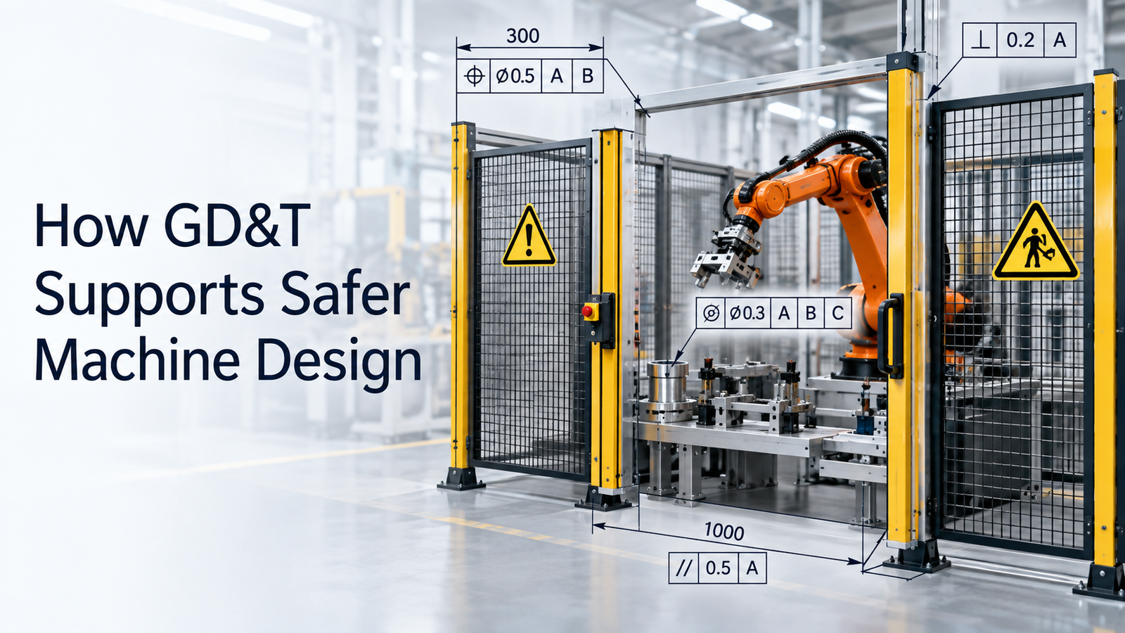
Geometric Dimensioning and Tolerancing, or GD&T, is usually associated with precision manufacturing and inspection. However, it can also support safer machine design.
Many machine-safety features depend on geometry. Guards must remain in the intended position. Mechanical stops must engage correctly. Bearings and shafts must stay aligned. Interlock brackets must hold sensors in the right location. Retaining parts must fit as designed. Structural interfaces must remain stable.
This makes geometric dimensioning and tolerancing safety an important topic for machine designers, manufacturing engineers, quality teams, and maintenance professionals.
GD&T does not replace machinery risk assessment, guarding, functional safety systems, or safety standards. Instead, it helps ensure that safety-related mechanical geometry is manufactured, inspected, assembled, and replaced consistently.
ISO 12100:2010 remains the current published international standard for machinery risk assessment and risk reduction, while ISO 1101:2017 remains current for geometrical tolerancing. ASME Y14.5-2018, reaffirmed in 2024, also remains in effect for GD&T practice.
This guide explains how GD&T can support safer machine design in practical engineering applications.
Key Steps and Considerations
1. Safety Depends on Correct Geometry
A machine can include the correct safety concept but still become unsafe if critical components are manufactured or installed in the wrong geometric relationship.
Examples include:
- A guard bracket positioned too far from the hazard
- A mechanical stop that does not engage fully
- A safety switch actuator that is misaligned
- A shaft with excessive runout
- A retaining feature positioned incorrectly
- A brake mounting face that is not perpendicular
These conditions may not always be obvious from basic size dimensions alone.
GD&T can help control the form, orientation, location, and runout characteristics that affect safe operation.
2. GD&T Supports Inherently Safer Design
ISO 12100 emphasizes risk reduction through design before relying only on protective measures or information for use.
GD&T can support this approach by helping designers define critical mechanical relationships clearly.
For example, if a locking pin must engage a hole before maintenance can begin, its position relative to the machine datum structure may be safety-critical.
A position tolerance can help ensure that the locking feature works consistently across production machines.
The safety comes from the mechanical concept, while GD&T helps preserve the geometry required for that concept to function.
3. Datums Create Reliable Safety References
Datums establish the reference framework for critical features.
Typical safety-related datum features may include:
- Machine base surfaces
- Guard mounting faces
- Shaft axes
- Locating holes
- Structural interfaces
A good datum system helps ensure that a safety feature is manufactured and inspected relative to the same surfaces that control its real machine location.
This reduces the risk of parts being acceptable on paper but incorrectly positioned in the final assembly.
4. Position Tolerance Helps Control Guard and Interlock Features
Position tolerance can be useful for features such as:
- Guard mounting holes
- Interlock brackets
- Locking-pin holes
- Retaining features
- Stop mounting points
If these features shift too far from their intended locations, the safety function may become unreliable.
For example, an interlock actuator may fail to engage correctly if its mounting holes allow excessive positional error.
Position tolerancing can control this relationship relative to functional datums.
5. Perpendicularity Helps Protect Critical Interfaces
Perpendicularity can be important where a surface or axis must remain square to a safety-critical reference.
Examples include:
- Brake mounting faces
- Shaft shoulders
- Mechanical stop faces
- Structural support plates
Poor perpendicularity may create uneven contact or incomplete engagement.
For example, if a mechanical stop face is significantly tilted, impact load may concentrate on a small area rather than the full intended contact surface.
GD&T helps define the orientation requirement directly.
6. Flatness Supports Stable Mounting
Safety-related equipment often depends on stable mounting surfaces.
Examples include:
- Brake assemblies
- Safety sensor brackets
- Structural mounting plates
- Guard supports
Poor flatness can cause:
- Distortion during tightening
- Misalignment
- Uneven loading
- Reduced contact area
A flatness tolerance can help ensure the surface provides stable support without requiring a datum reference.
7. Runout Control Supports Safer Rotating Machinery
Excessive runout in rotating components can create:
- Vibration
- Bearing overload
- Seal damage
- Unstable rotation
In severe cases, excessive vibration or component damage can contribute to mechanical hazards.
ISO 1101:2017 includes tolerances of form, orientation, location, and runout as part of its geometrical tolerancing framework.
Runout control can therefore support the mechanical integrity of:
- Shafts
- Spindles
- Couplings
- Rotors
- Pulleys
8. GD&T Helps Maintain Alignment
Alignment affects both reliability and safety.
Misalignment can increase:
- Heat
- Vibration
- Component stress
- Wear
- Unexpected failure
GD&T controls such as:
- Position
- Parallelism
- Perpendicularity
- Runout
can help preserve alignment between mechanical components.
For high-speed or high-load machinery, preventing geometric misalignment can reduce the likelihood of component failure.
9. GD&T Can Improve Mechanical Stop Reliability
Mechanical stops may be used to limit travel if:
- Sensors fail
- Control logic is incorrect
- A drive exceeds its expected position
The stop must be located and oriented correctly.
Relevant GD&T controls may include:
- Position
- Profile
- Perpendicularity
- Flatness
The stop structure itself must still be designed for the expected load and impact energy.
GD&T does not determine structural strength, but it helps ensure the physical stop is where the designer intended it to be.
10. GD&T Supports Retaining Features
Machine designs may use retaining features to prevent parts from separating or moving unexpectedly.
Examples include:
- Retaining-ring grooves
- Locking-pin locations
- Shaft shoulders
- Retaining plates
Incorrect location or orientation can reduce engagement.
GD&T can help control these critical relationships.
For example, a retaining groove may need controlled runout or position relative to a shaft datum.
11. GD&T Helps Control Interlock Mounting Geometry
Safety interlocks rely on both electrical or control functionality and mechanical alignment.
The mechanical design may include:
- Switch bracket
- Actuator
- Door
- Hinge
- Mounting holes
If the bracket or actuator is positioned incorrectly, the interlock may become difficult to engage or may require excessive adjustment.
A clear datum system and position tolerance can improve installation repeatability.
12. GD&T Improves Replacement-Part Consistency
Safety-related mechanical parts may need replacement after years of service.
Examples include:
- Guard brackets
- Stops
- Locking components
- Structural plates
- Sensor mounts
Replacement parts should preserve the original safety-related geometry.
GD&T supports interchangeability by defining the relationships that matter, not only nominal sizes.
ASME describes GD&T as a design language used to communicate form, fit, function, and interchangeability.
13. GD&T Supports Safer Maintenance
Maintenance often involves replacing or repairing components that affect machine geometry.
A repaired part may have the correct size but still be unsafe if:
- A hole is misplaced
- A surface is tilted
- A shaft has excessive runout
- A stop face is not flat
GD&T can provide measurable acceptance criteria before the machine is returned to service.
This is especially valuable for high-consequence mechanical interfaces.
14. Inspection Helps Verify Safety-Critical Geometry
A safety-related tolerance is useful only if it can be verified.
Inspection methods may include:
- Dial indicators
- Height gauges
- Functional gauges
- CMM inspection
The inspection approach should match the importance and complexity of the feature.
For example, a simple mechanical stop location may be checked using direct measurement, while complex datum-based geometry may require coordinate measurement.
15. Functional Gauging Can Verify Assembly Conditions
Some GD&T applications support functional gauges.
A gauge may verify whether a feature pattern or mating condition will assemble correctly.
This can be useful for repeated production of safety-related components such as:
- Locking holes
- Guard-mount patterns
- Retaining features
Functional gauging can provide fast confirmation that the part meets the intended assembly condition.
16. Avoid Unnecessarily Tight Safety Tolerances
Safety-critical does not automatically mean every tolerance should be extremely tight.
Excessive tolerance tightness can:
- Increase cost
- Increase rejection
- Complicate inspection
The tolerance should be based on the geometric variation that the safety function can actually accept.
Good engineering balances:
- Safety margin
- Manufacturing capability
- Inspection capability
17. Do Not Use GD&T as a Substitute for Risk Assessment
GD&T controls geometry.
It does not determine whether a machine concept is safe.
Machine safety still requires:
- Hazard identification
- Risk estimation
- Risk reduction
- Guarding
- Safe control systems
- Maintenance planning
ISO 12100 provides the overarching risk-assessment and risk-reduction framework for machine design.
GD&T should be used as one supporting engineering tool inside that broader process.
18. Do Not Rely on Tolerancing to Fix a Poor Safety Concept
If a safety mechanism is fundamentally unreliable, making tolerances tighter may not solve the real problem.
For example, if a guard bracket is too flexible, a tighter position tolerance does not address structural deflection.
The correct order is:
- Develop a sound safety concept.
- Design sufficient structural capacity.
- Define the geometric relationships that must be maintained.
- Apply GD&T where appropriate.
19. Use the Correct GD&T Standard Consistently
ISO 1101 and ASME Y14.5 are both major geometrical tolerancing systems.
They share many concepts but are not identical in every rule and default.
Engineering organizations should clearly identify which standard governs the drawing or model.
ISO 1101:2017 defines the ISO symbol language for geometrical specification and remains current.
ASME Y14.5-2018 (R2024) remains in effect and provides rules and recommended practices for GD&T on drawings, digital models, and related documents.
20. Keep Safety-Critical GD&T Under Revision Control
If a safety feature changes, its drawing or model definition may also need revision.
Examples include:
- Modified guard bracket
- New interlock position
- Revised mechanical stop
- Updated retaining feature
Revision control helps ensure that:
- Manufacturing
- Quality
- Maintenance
- Suppliers
all use the same approved requirement.
An obsolete GD&T definition can reintroduce a known problem.
GD&T Safety Checklist
| Safety Need | Useful Geometric Control |
|---|---|
| Guard bracket location | Position |
| Stop contact face | Flatness / Perpendicularity |
| Interlock alignment | Position |
| Rotating shaft | Runout |
| Parallel guard rail | Parallelism |
| Retaining feature | Position / Runout |
| Replacement component | Datum-based controls |
| Structural mounting interface | Flatness / Orientation |
Common GD&T Safety Mistakes
Avoid these mistakes:
- Using GD&T without a defined safety function
- Choosing datums unrelated to the machine assembly
- Applying extremely tight tolerances without justification
- Controlling size but ignoring orientation
- Ignoring runout on critical rotating components
- Failing to inspect safety-related geometry
- Replacing parts without checking datum-based requirements
- Mixing ISO and ASME rules without clarity
- Using GD&T instead of proper risk assessment
- Failing to update revisions after safety modifications
GD&T supports safer design when it protects the geometric relationships that a safety feature actually depends on.
Conclusion
GD&T can be an important supporting tool for machine safety.
A strong geometric dimensioning and tolerancing safety approach uses datum systems and geometric controls to preserve the location, orientation, form, and runout of safety-related mechanical features.
It can support reliable guard mounting, interlock alignment, mechanical stops, retaining features, rotating-component integrity, replacement-part interchangeability, and maintenance inspection.
ISO 12100:2010 remains the current published framework for machinery risk assessment and risk reduction. ISO 1101:2017 remains current for geometrical tolerancing, while ASME Y14.5-2018 (R2024) remains in effect and is widely used for communicating design intent, form, fit, function, and interchangeability.
The key principle is that GD&T should support the safety design, not replace it.
When risk reduction, mechanical design, tolerancing, manufacturing, and inspection are aligned, safety-critical features can be produced and maintained more consistently throughout the machine lifecycle.