
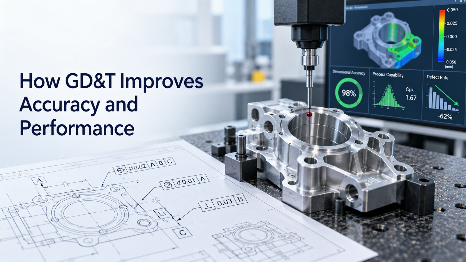
Geometric Dimensioning and Tolerancing, commonly known as GD&T, is one of the most effective tools for improving mechanical accuracy without simply making every dimension tighter.
Traditional plus/minus tolerancing mainly controls feature size and coordinate location. GD&T adds a more functional language for controlling form, orientation, location, and runout.
This makes geometric dimensioning and tolerancing efficiency especially valuable in machine design, precision manufacturing, inspection, assembly, and high-performance mechanical systems.
A good GD&T scheme can improve:
- Alignment
- Interchangeability
- Assembly repeatability
- Bearing performance
- Rotational accuracy
- Inspection consistency
- Manufacturing efficiency
ISO 1101:2017 remains the current published ISO standard for geometrical tolerancing, while ASME Y14.5-2018, reaffirmed in 2024, remains in effect and is widely used for dimensioning and tolerancing.
This guide explains how GD&T improves accuracy and performance and how engineers can use it more effectively.
Performance Improvement Steps
1. GD&T Controls Functional Geometry
Two parts can have the same nominal dimensions but perform differently because their geometry is different.
GD&T can control:
- Flatness
- Straightness
- Parallelism
- Perpendicularity
- Position
- Profile
- Runout
These characteristics often affect actual machine performance more than a simple linear dimension.
For example, a bearing bore may have the correct diameter but still create misalignment if its axis is not positioned or oriented correctly.
GD&T allows engineers to control these relationships directly.
2. Datum Systems Improve Repeatability
Datums provide a repeatable reference system for manufacturing, inspection, and assembly.
Typical datum features include:
- Mounting faces
- Shaft axes
- Bearing bores
- Locating holes
- Precision edges
A well-designed datum reference frame helps everyone evaluate the part from the same functional references.
This improves consistency between:
- Design
- Manufacturing
- Quality
- Assembly
Better datum strategy often improves accuracy without requiring tighter individual dimensions.
3. True Position Improves Hole and Feature Location
Position tolerancing is widely used for:
- Hole patterns
- Pins
- Bores
- Fastener locations
- Locating features
Traditional coordinate tolerances may create rectangular tolerance zones.
Position tolerance can create a more functional cylindrical zone around the theoretically exact location.
This can improve both assembly acceptance and inspection efficiency.
For example, a bolt-hole pattern can be controlled based on whether the fasteners will actually assemble correctly rather than by overly restrictive coordinate dimensions.
4. Basic Dimensions Improve Design Clarity
Basic dimensions define the theoretically exact location or orientation of features.
They work together with geometric tolerances.
This helps separate:
- Nominal geometry
- Allowed variation
That makes the drawing easier to interpret.
Instead of mixing coordinate tolerances throughout the drawing, engineers can define exact design intent with basic dimensions and control variation using a feature control frame.
5. Flatness Improves Mounting Performance
Mounting surfaces often need controlled flatness.
Applications include:
- Motor bases
- Gearbox mounts
- Bearing housings
- Linear guide supports
- Fixture plates
Poor flatness can create:
- Distortion
- Uneven contact
- Misalignment
- Guide binding
- Vibration
A flatness tolerance controls the surface independently of a datum.
This is useful when the surface itself must provide stable and uniform support.
6. Parallelism Improves Linear-Motion Performance
Parallelism is important for:
- Guide rails
- Sliding surfaces
- Shaft arrangements
- Fixture surfaces
Poor parallelism can increase:
- Friction
- Wear
- Internal loading
- Position error
A parallelism tolerance relative to a functional datum can help ensure components remain correctly oriented during assembly and operation.
This is especially important in precision linear-motion systems.
7. Perpendicularity Improves Alignment
Perpendicularity controls how a feature is oriented relative to a datum.
Applications include:
- Shaft shoulders
- Motor mounting faces
- Bearing seats
- Machine columns
- Fixture surfaces
Poor perpendicularity can create angular misalignment.
This may affect:
- Bearing life
- Coupling performance
- Tool accuracy
- Assembly consistency
Controlling orientation directly can improve machine performance more effectively than tightening unrelated linear dimensions.
8. Runout Improves Rotational Accuracy
Runout controls are important for rotating components.
Typical applications include:
- Shafts
- Spindles
- Pulleys
- Couplings
- Rotors
Excessive runout can cause:
- Vibration
- Uneven bearing load
- Seal wear
- Poor rotational accuracy
Circular runout controls individual circular sections during rotation.
Total runout controls the complete referenced surface along its length.
Using the correct runout control can improve dynamic performance and reduce vibration.
9. Profile Can Control Complex Geometry Efficiently
Profile is one of the most flexible GD&T controls.
It can control complex surfaces that would otherwise require many coordinate dimensions.
Applications may include:
- Castings
- Aerodynamic surfaces
- Complex machined profiles
- Plastic components
A profile tolerance can simplify the drawing while controlling the complete surface relative to functional datums.
This can improve communication and reduce over-dimensioning.
10. MMC Can Improve Assembly Efficiency
Maximum Material Condition, or MMC, is often used with position tolerance.
For a hole, MMC represents the smallest allowed hole size.
For a pin, MMC represents the largest allowed pin size.
Using MMC can provide bonus geometric tolerance as the feature moves away from its maximum-material condition.
This can improve manufacturability while still protecting assembly function.
It is especially useful for:
- Clearance holes
- Fastener patterns
- Pin-and-hole assemblies
11. GD&T Can Reduce Unnecessary Tight Tolerances
One of the biggest performance and cost advantages of GD&T is that it can control the geometry that matters without tightening every size dimension.
For example, instead of tightly controlling two coordinate dimensions for a hole, position tolerance can control the feature in a more function-oriented way.
This may allow more manufacturing variation while still maintaining assembly performance.
The result can be:
- Better manufacturability
- Lower rejection rates
- Improved interchangeability
12. GD&T Improves Tolerance Stack-Up Control
Assemblies contain multiple sources of variation.
These may include:
- Hole position
- Shaft position
- Part thickness
- Spacer size
- Datum transfer
GD&T helps engineers control the functional relationships more directly.
However, it does not eliminate the need for tolerance-stack analysis.
Critical assemblies should still be evaluated as complete tolerance chains.
Combining GD&T with tolerance-stack analysis can improve assembly predictability.
13. GD&T Improves Part Interchangeability
Interchangeability means that one acceptable part can be replaced by another acceptable part without custom adjustment.
This is important in:
- Mass production
- Spare parts
- Maintenance
- Supplier sourcing
ASME Y14.5 emphasizes standardized dimensioning and tolerancing for form, fit, function, and interchangeability.
Clear geometric controls reduce dependence on individual supplier interpretation.
14. GD&T Improves Inspection Efficiency
A good GD&T scheme tells inspectors:
- What feature matters
- Which datum to use
- What geometric condition to evaluate
This can make inspection more focused.
Instead of checking many loosely connected dimensions, quality teams can inspect the functional geometric requirement.
This is especially useful with:
- Coordinate Measuring Machines
- Functional gauges
- Automated metrology
15. Functional Gauging Can Speed Production Checks
Some GD&T applications, especially position at MMC, can support functional gauging.
A functional gauge can quickly verify whether a part will assemble under worst-case conditions.
Benefits may include:
- Faster inspection
- Consistent acceptance
- Reduced measurement complexity
Functional gauges are especially useful in repeated high-volume production.
16. CMM Inspection Supports Complex GD&T
Coordinate Measuring Machines are commonly used for complex geometric inspection.
They can evaluate characteristics such as:
- Position
- Profile
- Orientation
- Form
NIST has studied GD&T implementation and downstream inspection because digital interpretation must remain consistent between design and metrology systems.
This becomes increasingly important as manufacturing moves toward model-based workflows.
17. GD&T Improves Supplier Communication
A supplier should understand not only the nominal dimensions but also the functional geometric requirements.
GD&T creates a structured language for this purpose.
Better communication can reduce:
- Clarification questions
- Rework
- Inspection disagreement
- Supplier variation
This improves both engineering efficiency and product consistency.
18. GD&T Helps Optimize Precision Where It Matters
Not every surface needs the same precision.
A strong GD&T strategy concentrates control on:
- Critical interfaces
- Alignment features
- Rotating surfaces
- Locating features
Noncritical geometry can remain less tightly controlled.
This helps engineering teams achieve the required machine performance without unnecessary manufacturing burden.
19. GD&T Supports Model-Based Engineering
Modern CAD systems can store GD&T as Product Manufacturing Information.
This allows geometric requirements to move digitally into:
- CAM
- Inspection
- Quality systems
- Digital product-definition workflows
NIST research on CAD-based GD&T highlights the importance of correct semantic representation in these digital workflows.
As model-based engineering grows, GD&T becomes even more important because it provides structured, machine-readable design intent.
20. Good GD&T Improves Overall Design Performance
When applied correctly, GD&T can improve more than dimensional accuracy.
It can improve:
- Assembly repeatability
- Bearing alignment
- Rotational quality
- Guide performance
- Supplier consistency
- Inspection speed
- Replacement-part interchangeability
The objective is not to add more symbols to a drawing.
The objective is to communicate functional geometry more effectively.
GD&T Performance Optimization Checklist
| Performance Need | Useful GD&T Approach |
|---|---|
| Stable mounting | Flatness |
| Guide alignment | Parallelism |
| Shaft shoulder accuracy | Perpendicularity |
| Hole pattern assembly | Position |
| Rotational accuracy | Runout |
| Complex surface control | Profile |
| Interchangeability | Datum-based position |
| Fast inspection | Functional gauging |
| Assembly prediction | GD&T + tolerance stack-up |
Common GD&T Optimization Mistakes
Avoid these mistakes:
- Tightening every tolerance instead of controlling function
- Choosing nonfunctional datums
- Using position without proper basic dimensions
- Applying MMC automatically
- Using flatness when orientation is required
- Selecting runout without understanding the rotating datum
- Overusing profile
- Ignoring inspection capability
- Failing to analyze assembly tolerance stack-up
- Adding GD&T without a performance reason
A simpler, function-based tolerance scheme is usually more effective than a drawing filled with unnecessary controls.
Conclusion
GD&T can significantly improve mechanical accuracy and performance when it is applied around design function.
A strong geometric dimensioning and tolerancing efficiency approach uses datums, position, flatness, parallelism, perpendicularity, runout, profile, and material-condition modifiers to control the geometric relationships that matter most.
ISO 1101:2017 remains the current published ISO standard for geometrical tolerancing, while ASME Y14.5-2018 (R2024) remains in effect and supports standardized communication of form, fit, function, and interchangeability.
The biggest advantage of GD&T is not tighter tolerances.
It is better control.
By controlling functional geometry instead of simply reducing every dimensional tolerance, engineers can improve assembly accuracy, rotational performance, repeatability, inspection efficiency, and interchangeability while avoiding unnecessary manufacturing cost.