
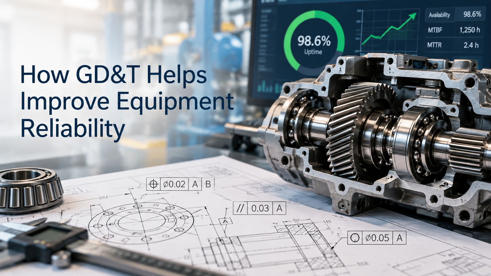
Geometric Dimensioning and Tolerancing, commonly called GD&T, is often associated with design and manufacturing, but it also has a major impact on equipment reliability and maintenance.
A machine can contain high-quality bearings, shafts, couplings, guides, and gears and still suffer repeated failures if the geometry around those components is incorrect.
Misalignment, excessive runout, poor flatness, incorrect position, and inconsistent replacement parts can all reduce service life.
This is why geometric dimensioning and tolerancing maintenance practices are important for maintenance, reliability, manufacturing, and inspection teams.
GD&T helps define how critical surfaces and features should relate to each other, making it easier to preserve the original design intent during manufacturing, repair, inspection, and replacement.
ISO 1101:2017 remains the current published ISO standard for geometrical tolerancing. ASME Y14.5-2018, reaffirmed in 2024, also remains in effect and is widely used for dimensioning and tolerancing.
This guide explains how GD&T can improve equipment reliability throughout the machine lifecycle.
Key Reliability Practices
1. GD&T Controls Geometry, Not Just Size
Traditional plus/minus dimensions mainly control size and location.
GD&T can also control:
- Form
- Orientation
- Location
- Runout
Common controls include:
- Flatness
- Straightness
- Parallelism
- Perpendicularity
- Position
- Circular runout
- Total runout
These geometric relationships often have a direct effect on machine performance.
For example, a bearing bore may have the correct diameter but still create a reliability problem if it is not aligned correctly with the mating shaft.
2. Datum Systems Preserve Functional Alignment
Datums establish the reference system used to locate and orient critical features.
Typical datums may include:
- Mounting faces
- Bearing bores
- Shaft axes
- Locating holes
- Precision guide surfaces
A good datum structure helps manufacturing, inspection, and maintenance teams reference the part in the same functional way.
This is especially important when replacement or repaired components must return the machine to its original geometry.
Without consistent datums, parts can be dimensionally acceptable but still assemble differently.
3. GD&T Helps Reduce Bearing Misalignment
Bearing life can be reduced by misalignment.
Possible causes include:
- Housing bores not aligned
- Mounting faces not perpendicular
- Shaft shoulders not square
- Excessive shaft runout
GD&T can define these geometric requirements more directly than simple linear dimensions.
For example:
- Perpendicularity may control a bearing shoulder relative to the shaft axis.
- Position may control bearing bore location.
- Runout may control rotating surfaces.
This helps reduce unwanted bearing loading.
4. Runout Control Improves Rotating Equipment Reliability
Runout is especially important for:
- Shafts
- Couplings
- Pulleys
- Gears
- Rotors
Excessive runout can cause:
- Vibration
- Seal wear
- Uneven bearing loading
- Coupling stress
- Poor rotational accuracy
ISO 1101 includes geometric controls for runout as part of its framework for form, orientation, location, and run-out tolerances.
By defining acceptable runout, designers provide maintenance and inspection teams with measurable criteria for repair and replacement.
5. Flatness Can Improve Mounting Reliability
Machine components often depend on flat mounting surfaces.
Examples include:
- Gearboxes
- Motors
- Bearing housings
- Linear guide bases
Poor flatness can distort components during tightening.
This may create:
- Misalignment
- Uneven bearing loads
- Guide binding
- Vibration
A flatness tolerance helps ensure that the mounting surface provides uniform support.
During maintenance, the same tolerance can be used to determine whether a damaged or repaired surface remains acceptable.
6. Parallelism Helps Maintain Guide Accuracy
Linear guides and sliding mechanisms often require parallel reference surfaces.
Poor parallelism may create:
- Binding
- Uneven loading
- Increased friction
- Premature wear
GD&T can define parallelism relative to a functional datum.
This is useful when:
- Machining replacement guide bases
- Repairing worn surfaces
- Reinstalling machine components
Consistent geometric control improves both performance and life.
7. Perpendicularity Helps Control Assembly Geometry
Perpendicularity is important where surfaces or axes must remain at 90 degrees.
Applications include:
- Shaft shoulders
- Motor mounts
- Bearing seats
- Fixture plates
- Guide supports
If a bearing shoulder is not perpendicular to the shaft axis, the bearing may not seat correctly.
This can generate unwanted internal loads.
A perpendicularity tolerance helps prevent this condition.
8. Position Tolerances Improve Replacement-Part Interchangeability
Replacement parts should fit without extensive rework.
Position tolerances can control:
- Hole patterns
- Bearing bores
- Locating pins
- Mounting features
This supports interchangeability.
For maintenance teams, interchangeability means:
- Faster replacement
- Less on-site modification
- Lower downtime
ASME Y14.5 emphasizes standardized dimensioning and tolerancing to communicate form, fit, function, and interchangeability.
9. GD&T Helps Troubleshoot Repeated Failures
Repeated component failure may be caused by surrounding geometry.
For example:
Repeated bearing failure
Potential geometric causes:
- Housing bores out of alignment
- Shaft runout
- Incorrect shoulder perpendicularity
- Distorted mounting face
GD&T gives engineers a structured way to investigate these conditions.
Instead of replacing the failed part only, the maintenance team can inspect the geometric relationships that may be creating the failure.
10. GD&T Improves Inspection Consistency
A reliability program depends on repeatable inspection.
GD&T helps define:
- What should be measured
- Which datum should be used
- How geometry should be evaluated
NIST has noted that GD&T is created as part of the design process and can be reused downstream in production and inspection.
This improves consistency between:
- Engineering
- Manufacturing
- Quality
- Maintenance
11. CMM Inspection Can Support Reliability Decisions
Coordinate Measuring Machines can inspect complex geometric relationships.
They may be used to measure:
- Position
- Flatness
- Perpendicularity
- Runout-related geometry
- Profile
For high-value machine components, CMM inspection can help determine whether a repaired component is still within the specified geometric limits.
This reduces subjective repair decisions.
12. GD&T Helps Control Repaired Components
Repair processes can change geometry.
Examples include:
- Welding
- Machining
- Metal spraying
- Grinding
After repair, the component may have the correct nominal dimensions but poor geometric relationships.
GD&T allows the repaired component to be checked against the original functional requirement.
This is especially important for:
- Bearing housings
- Gearbox interfaces
- Machine frames
- Precision fixtures
13. GD&T Improves Spare-Part Quality
Spare parts may come from:
- Original manufacturers
- Local machine shops
- Alternate suppliers
A clear GD&T specification reduces dependence on one supplier's interpretation.
The part can be produced against defined geometric requirements.
This supports consistent spare quality across different sources.
14. GD&T Reduces the Risk of "Looks Correct" Repairs
A repaired part may look correct and measure correctly with basic tools while still containing geometric errors.
For example:
- Bore axis shifted
- Face not perpendicular
- Surface distorted
- Shaft bent
Basic dimensional checks may miss these conditions.
GD&T provides additional controls where geometry matters.
15. Maintenance Teams Can Use GD&T as Acceptance Criteria
Maintenance decisions are often based on whether a component can be:
- Reused
- Repaired
- Replaced
GD&T can provide acceptance criteria.
Examples:
- Maximum flatness error
- Maximum runout
- Position tolerance
- Parallelism limit
This makes decisions more objective.
16. GD&T Helps Preserve Machine Accuracy After Rebuilds
Major machine rebuilds may involve replacement of:
- Shafts
- Housings
- Frames
- Guide surfaces
If only nominal dimensions are considered, original alignment may be lost.
Datum systems and geometric tolerances help preserve the intended machine geometry.
This is especially valuable for precision machinery.
17. Revision Control Is Important for GD&T
Geometric requirements may change during design improvement.
A revised drawing may include:
- New datum structure
- Updated position tolerance
- Improved runout control
- Changed mounting requirement
Maintenance teams should always use the latest approved revision.
Using an old drawing can reintroduce a known reliability problem.
18. Do Not Overuse GD&T
More geometric controls do not automatically improve reliability.
Poorly chosen or excessively tight controls can increase:
- Manufacturing cost
- Inspection difficulty
- Repair cost
GD&T should be used where geometric relationships affect:
- Fit
- Function
- Alignment
- Reliability
A simple noncritical bracket does not need the same level of geometric control as a bearing housing or precision spindle.
19. Maintenance and Design Teams Should Share Failure Data
Reliability improves when maintenance feedback is used to improve drawings.
For example, repeated failures may reveal the need for:
- Better runout control
- Improved datum selection
- Tighter perpendicularity
- Better mounting flatness
This creates a feedback loop:
- Design
- Manufacture
- Operate
- Fail
- Inspect
- Improve Drawing
GD&T can become part of continuous machine improvement.
20. Train Maintenance Teams to Read Critical GD&T
Maintenance technicians do not need to become full-time GD&T specialists, but they should understand critical symbols used on their equipment.
Useful concepts include:
- Datum
- Flatness
- Parallelism
- Perpendicularity
- Position
- Runout
This helps technicians communicate more effectively with quality and engineering teams.
GD&T Reliability Checklist
| Reliability Area | Useful GD&T Control |
|---|---|
| Mounting surface | Flatness |
| Parallel guides | Parallelism |
| Bearing shoulder | Perpendicularity |
| Hole pattern | Position |
| Rotating shaft | Runout |
| Replacement part | Datum-based position |
| Repaired housing | Form and orientation checks |
| Machine rebuild | Datum alignment |
Common GD&T Maintenance Mistakes
Avoid these mistakes:
- Checking only basic size dimensions
- Ignoring datum references
- Replacing bearings without checking surrounding geometry
- Accepting repaired surfaces without geometric inspection
- Using outdated drawing revisions
- Assuming visually similar spare parts are equivalent
- Applying unnecessarily tight GD&T to every feature
- Failing to share recurring failure data with design engineering
Good GD&T improves reliability when it is focused on the geometric relationships that matter to machine function.
Conclusion
Geometric tolerancing is an important reliability tool.
A strong geometric dimensioning and tolerancing maintenance approach helps control alignment, runout, flatness, parallelism, perpendicularity, and feature position throughout manufacturing, repair, inspection, and replacement.
ISO 1101:2017 remains the current ISO standard defining the symbol language and interpretation rules for geometrical tolerancing, while ASME Y14.5-2018 (R2024) remains in effect and is widely used for dimensioning and tolerancing.
GD&T does not prevent every machine failure.
However, it helps engineers and maintenance teams identify and control geometric conditions that can create repeated bearing failures, vibration, guide wear, seal damage, and assembly problems.
When design, inspection, and maintenance teams use the same geometric references, equipment can be repaired and rebuilt more consistently, improving long-term reliability.