
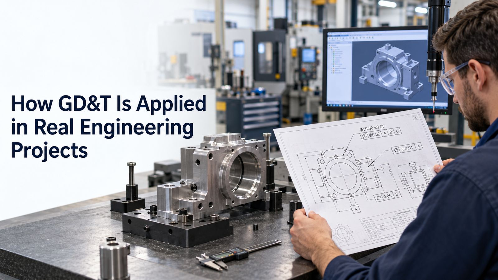
Geometric Dimensioning and Tolerancing, commonly called GD&T, becomes most useful when it moves beyond classroom symbols and is applied to real mechanical parts and assemblies.
In practical engineering, GD&T is used to control how components fit, align, rotate, locate, and assemble. It helps designers communicate functional requirements to manufacturing, inspection, suppliers, and maintenance teams.
This makes geometric dimensioning and tolerancing applications important in projects involving shafts, bearing housings, machine frames, hole patterns, fixtures, linear guides, gearboxes, rotating assemblies, and precision equipment.
ISO 1101:2017 remains the current published ISO standard for geometrical tolerancing, while ASME Y14.5-2018, reaffirmed in 2024, remains in effect and is widely used in engineering practice. citeturn485716search0turn485716search1
This guide explains how GD&T is applied in real engineering projects and how engineers connect tolerance symbols with actual machine function.
Key Applications
1. Start With Function, Not Symbols
A common mistake is to begin by asking:
Which GD&T symbol should I use?
A better question is:
What relationship must this feature maintain for the machine to work correctly?
For each critical feature, determine:
- What locates the part?
- What must align?
- What must rotate accurately?
- What features must assemble together?
- What geometric error could cause failure?
GD&T should then be selected to control that function.
For example, if a motor mounting face must remain square to a shaft axis, perpendicularity may be more meaningful than simply tightening multiple coordinate dimensions.
2. Applying GD&T to Bearing Housings
Bearing housings are a common real-world GD&T application.
Important requirements may include:
- Bore position
- Bore alignment
- Mounting-face flatness
- Bore orientation
- Shoulder location
If two bearing bores are misaligned, the shaft may experience:
- Excessive load
- Heat
- Vibration
- Premature bearing failure
A practical tolerance scheme might use:
- A mounting surface as datum A
- A locating edge or bore as datum B
- Position or orientation controls on the bearing bores
The exact scheme depends on how the housing functions and is assembled.
3. Applying GD&T to Shafts
Shafts often require geometric control beyond diameter tolerances.
Important characteristics may include:
- Runout
- Straightness
- Shoulder perpendicularity
- Bearing-seat relationships
- Groove location
For example, a bearing seat may have the correct diameter but still cause vibration if the shaft surface has excessive runout relative to the functional datum axis.
Circular or total runout may be used depending on what part of the rotating geometry must be controlled.
4. Applying GD&T to Hole Patterns
Hole patterns are among the most common applications of position tolerance.
Examples include:
- Motor mounting plates
- Flanges
- Covers
- Fixture plates
- Structural brackets
Traditional coordinate dimensioning may control each hole independently.
Position tolerance allows the hole pattern to be controlled relative to functional datums.
This is especially useful when the actual requirement is:
Will the mating part assemble correctly?
A properly designed position tolerance can improve interchangeability without making every X and Y dimension unnecessarily tight.
5. Applying GD&T to Linear Guide Mounting
Linear guides depend heavily on geometric relationships.
Critical conditions may include:
- Mounting-face flatness
- Rail parallelism
- Hole position
- Reference-face orientation
If guide rails are poorly aligned, the machine may experience:
- Binding
- High friction
- Uneven block loading
- Reduced life
GD&T can help define the geometry required to maintain guide alignment.
For example, one mounting face may establish datum A, while another reference edge establishes datum B.
Parallelism or position controls can then protect the guide relationship.
6. Applying GD&T to Motor and Gearbox Mounting
Motor and gearbox assemblies require good alignment.
Possible GD&T requirements include:
- Mounting-face flatness
- Shaft-axis position
- Perpendicularity
- Hole-pattern position
Misalignment can affect:
- Coupling life
- Bearing load
- Noise
- Vibration
Instead of relying only on general machining tolerances, the drawing can control the critical interface directly.
7. Applying GD&T to Flanges
Flanges are used throughout industrial machinery.
Applications include:
- Pipe interfaces
- Motor connections
- Gearbox interfaces
- Rotating assemblies
Important features may include:
- Bolt-hole pattern
- Face flatness
- Bore position
- Face orientation
Position tolerance can control the bolt pattern, while runout or perpendicularity may be relevant for rotating flange faces.
8. Applying GD&T to Fixtures
Fixtures require repeatable part location.
Typical datum features may include:
- Base surface
- Locating pin
- Side locator
GD&T can control:
- Pin position
- Clamp location
- Rest-pad flatness
- Locator orientation
A fixture must reproduce the same workpiece position across many cycles.
Good datum design is therefore especially important.
9. Applying GD&T to Precision Plates
Precision plates often contain:
- Hole patterns
- Guide holes
- Dowel holes
- Mounting surfaces
GD&T may use:
- Flatness
- Position
- Perpendicularity
- Parallelism
The tolerance scheme should reflect how the plate is mounted and what components depend on it.
For example, dowel-hole position may be more critical than clearance-hole position.
10. Applying GD&T to Rotating Components
Rotating components require special attention to datum axes and runout.
Applications include:
- Pulleys
- Gears
- Rotors
- Couplings
- Spindles
Excessive runout may create:
- Vibration
- Uneven load
- Poor surface finish
- Seal wear
The datum axis should represent the actual functional rotation.
This is one of the most important decisions in a rotating-part drawing.
11. Applying GD&T to Welded Frames
Welded frames are not usually controlled like precision machined parts.
However, selected geometric controls may still be useful for critical interfaces.
Examples include:
- Flatness of machined mounting pads
- Position of mounting holes
- Parallelism of guide surfaces
The goal is not to apply tight GD&T across the entire welded structure.
Instead, control the interfaces where precision components mount.
This avoids unnecessary fabrication cost.
12. Using GD&T With Machined Datum Pads
Large fabricated machines often use machined pads to create accurate references on otherwise less precise structures.
These pads may support:
- Linear rails
- Motors
- Gearboxes
- Bearings
GD&T can define relationships between those pads.
This is a practical way to combine economical fabrication with controlled precision where required.
13. Applying MMC to Clearance-Hole Assemblies
Maximum Material Condition can be useful in bolted assemblies.
Consider a clearance hole.
At MMC, the hole is at its smallest permitted size.
If the actual hole becomes larger, additional positional variation may be acceptable while the bolt still fits.
This can provide bonus tolerance.
In high-volume manufacturing, this may reduce rejection while still protecting assembly.
14. Using Functional Gauges
Functional gauges are a practical way to verify certain GD&T requirements.
They may be used for:
- Hole patterns
- Pin patterns
- Mating features
A functional gauge can simulate the mating component and quickly answer:
Will this part assemble?
This can be faster than measuring every feature separately.
15. Applying GD&T in Supplier Drawings
When a supplier manufactures a precision component, the drawing should clearly communicate:
- Governing standard
- Datum scheme
- Geometric controls
- Material requirements
- Inspection needs
ASME states that GD&T provides a common language across product realization and helps reduce manufacturing guesswork. citeturn485716search1turn485716search2
This becomes especially important when multiple suppliers produce interchangeable parts.
16. Applying GD&T During Design Reviews
GD&T should be reviewed before drawing release.
A practical review asks:
- Does the datum scheme match function?
- Is every control necessary?
- Are tolerances realistic?
- Can they be inspected?
- Do they support assembly?
Mechanical, manufacturing, and quality engineers should ideally participate in the review for critical components.
17. Applying GD&T During Inspection Planning
Inspection should not be considered after the drawing is finished.
For each geometric control, decide how it can be verified.
Possible methods include:
- Surface plate
- Dial indicator
- Functional gauge
- Height gauge
- Coordinate Measuring Machine
If a tolerance is difficult to inspect, engineers should confirm that it is truly required.
18. Applying GD&T During Failure Troubleshooting
GD&T can help diagnose recurring failures.
For example:
Repeated bearing failure
Possible checks:
- Shaft runout
- Housing bore position
- Shoulder perpendicularity
- Mounting-face flatness
A failed component may be only the symptom.
The real cause may be geometric error in the surrounding assembly.
19. Applying GD&T to Replacement Parts
Replacement parts should preserve the same functional geometry as the original.
This is important for:
- Shafts
- Bearing housings
- Brackets
- Fixtures
- Guide supports
A replacement part with the same nominal dimensions may not perform correctly if geometric relationships are missing.
GD&T improves interchangeability across suppliers and production batches.
20. Applying GD&T in Model-Based Definition
Modern CAD systems increasingly allow GD&T to be embedded directly into the 3D model as Product Manufacturing Information.
ISO 1101 notes that geometric specifications may be attached to 3D CAD models through ISO 16792 rather than only through visible 2D annotations. citeturn485716search0
This allows geometric requirements to support:
- Manufacturing
- Inspection
- Digital product definition
Model-based workflows can reduce duplicate data entry, but the semantic data must be validated carefully.
21. Real Project Example: Bearing-Supported Shaft
Consider a shaft supported by two bearings.
Important functional relationships may include:
- Shaft bearing-seat diameter
- Shaft runout
- Housing bore alignment
- Shoulder perpendicularity
A practical GD&T strategy might:
- Define the primary functional axis.
- Control rotating surfaces relative to that axis.
- Control bearing shoulders for orientation.
- Control housing bores from common functional datums.
- Inspect the finished assembly for alignment.
The exact tolerance values depend on the application.
The important point is that the tolerance scheme follows the load and alignment function.
22. Real Project Example: Motor Mounting Plate
A motor mounting plate may require:
- Flat mounting face
- Accurate bolt-hole pattern
- Correct shaft opening location
A practical approach may use:
- Flatness on the mounting surface
- Datums based on the machine interface
- Position on bolt holes
- Basic dimensions for hole locations
This can provide better assembly control than independent coordinate tolerances alone.
23. Real Project Example: Linear Slide Assembly
A linear slide may include:
- Two guide rails
- Carriage
- Ball screw
- Motor
Key geometric relationships may include:
- Guide parallelism
- Ball screw alignment
- Motor mounting orientation
- Bearing support location
GD&T should focus on these functional interfaces.
Over-tolerancing every frame dimension would increase cost without necessarily improving motion performance.
Practical GD&T Application Checklist
| Project Feature | Typical GD&T Consideration |
|---|---|
| Bearing housing | Position / orientation |
| Shaft | Runout / perpendicularity |
| Hole pattern | Position |
| Linear guide | Flatness / parallelism |
| Motor mount | Flatness / position |
| Flange | Position / runout |
| Fixture | Datum-based position |
| Precision plate | Flatness / position |
| Welded frame | Critical machined interfaces |
| Replacement part | Functional datum scheme |
Common Application Mistakes
Avoid these mistakes:
- Choosing symbols before understanding function
- Using nonfunctional datums
- Applying tight GD&T to every feature
- Ignoring assembly tolerance stack-up
- Using runout with the wrong datum axis
- Applying position without basic dimensions
- Ignoring inspection capability
- Failing to state the governing standard
- Allowing suppliers to interpret critical geometry differently
- Treating GD&T as separate from mechanical design
GD&T works best when it is integrated with design, manufacturing, inspection, and maintenance.
Conclusion
Real geometric dimensioning and tolerancing applications are built around function.
GD&T is used to control bearing alignment, shaft runout, hole patterns, linear-guide geometry, motor mounts, fixtures, rotating components, precision interfaces, replacement parts, and model-based product definitions.
ISO 1101:2017 remains the current published ISO standard and defines the symbol language and interpretation rules for geometric tolerancing. ASME Y14.5-2018 (R2024) remains in effect and provides a widely used framework for communicating form, fit, function, and interchangeability. citeturn485716search0turn485716search1
The value of GD&T comes from connecting tolerance controls to the real mechanical requirement.
When engineers choose datums and geometric controls based on how parts actually locate, move, rotate, and assemble, GD&T becomes a practical tool for improving quality, reliability, interchangeability, and manufacturing consistency.