
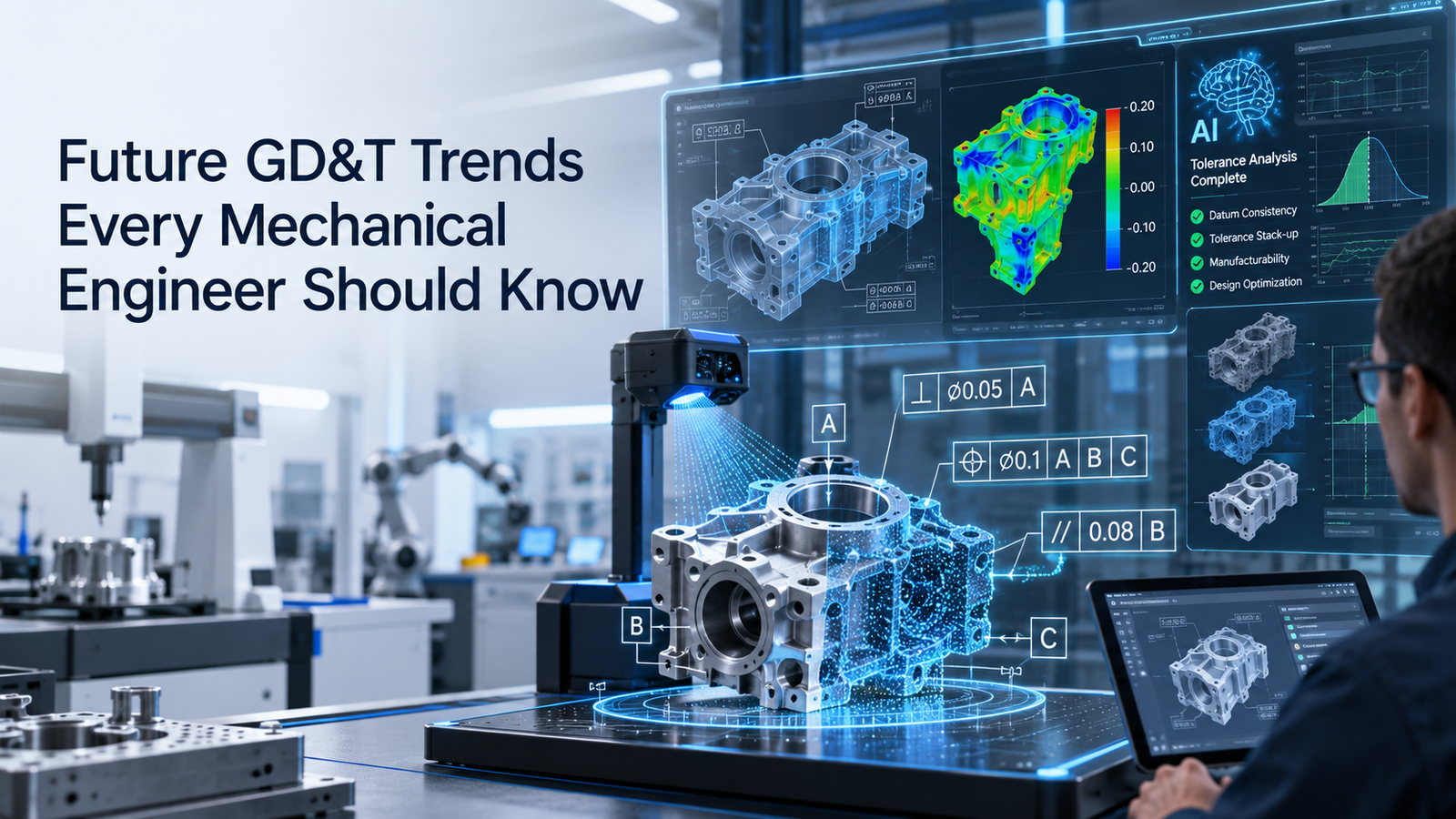
Geometric Dimensioning and Tolerancing, commonly known as GD&T, is moving beyond traditional 2D drawing annotations.
Mechanical engineers still need to understand datums, position, profile, runout, flatness, perpendicularity, material-condition modifiers, and tolerance zones. However, the way this information is created, shared, checked, and used across manufacturing is changing rapidly.
The most important geometric dimensioning and tolerancing trends include semantic Product Manufacturing Information (PMI), Model-Based Definition (MBD), automated GD&T validation, AI-assisted tolerancing, digital-thread integration, model-based inspection, and more drawingless manufacturing workflows.
ISO 1101:2017 remains the current published ISO foundation for geometrical tolerancing. At the same time, ISO is developing the next edition of ISO 16792 for digital product-definition data practices. The 2026 draft supports both 3D model-only workflows and hybrid workflows combining a 3D model with a 2D drawing.
This guide explains the major GD&T trends mechanical engineers should understand as product development becomes increasingly digital.
Key Technology Trends
1. GD&T Is Moving Into the 3D Model
Traditional GD&T is commonly communicated through a 2D engineering drawing.
A newer workflow places GD&T directly into the 3D CAD model.
This may include:
- Datum features
- Basic dimensions
- Position tolerances
- Profile tolerances
- Surface texture
- Material notes
- Manufacturing notes
The annotated 3D model can become part of the official product definition.
ISO 1101 already recognizes that geometrical specifications may be attached indirectly to a 3D CAD model through ISO 16792 rather than being shown only as visible drawing annotations.
This trend is central to modern model-based engineering.
2. Model-Based Definition Will Expand
Model-Based Definition uses a digital 3D model as a primary source of product information.
The model can include both geometry and Product Manufacturing Information.
ISO/DIS 16792:2026 supports two application methods:
- 3D model-only
- 3D model with a 2D digital drawing
This is important because industry is unlikely to move from drawings to fully drawingless workflows overnight.
Hybrid workflows will remain common while organizations build confidence in model-based processes.
3. Semantic PMI Will Become More Important
There is an important difference between graphical PMI and semantic PMI.
Graphical PMI is primarily designed for people to read.
Semantic PMI contains structured information that software can interpret.
NIST explains that semantic PMI allows engineering software to process GD&T and other product information directly.
This can support automation in:
- CAD
- CAM
- CMM programming
- Inspection
- Quality systems
This is one of the most important future trends because GD&T becomes data, not just a visual symbol.
4. GD&T Will Become More Machine-Readable
Future engineering systems will increasingly need to interpret tolerance information automatically.
For example, software may identify:
- Controlled feature
- Datum reference frame
- Tolerance value
- Material-condition modifier
- Basic geometry
This can reduce manual interpretation between design and manufacturing.
Instead of an engineer reading a drawing and manually entering a tolerance into another system, the information may flow digitally.
5. Automated GD&T Validation Will Increase
GD&T mistakes are common because tolerance schemes can become complex.
Future CAD systems will increasingly perform automatic checks for:
- Missing datums
- Invalid feature control frames
- Missing basic dimensions
- Conflicting specifications
- Incomplete PMI
Automated validation can help detect documentation errors before drawings or models are released.
This will not replace engineering judgment.
Software may know whether a control is syntactically valid but not whether it represents the best functional design.
6. AI-Assisted Tolerancing Will Grow
Artificial intelligence may increasingly assist with tolerance design.
Future engineering tools may help:
- Recommend datum structures
- Suggest geometric controls
- Detect over-tolerancing
- Identify missing specifications
- Compare similar historical designs
AI could also use manufacturing data to suggest tolerance ranges that balance function and process capability.
However, engineers will still need to validate:
- Function
- Safety
- Manufacturability
- Inspection
AI assistance should support engineering decisions rather than replace responsibility for design intent.
7. AI Could Help Reduce Over-Tolerancing
Over-tolerancing increases manufacturing and inspection cost.
AI systems may eventually analyze:
- Design geometry
- Assembly relationships
- Manufacturing capability
- Historical inspection data
and highlight tolerances that appear unnecessarily tight.
This could help engineers focus precision only where it affects function.
The economic impact could be significant in high-volume manufacturing.
8. Digital Threads Will Connect GD&T Across the Lifecycle
A digital thread connects product information across engineering and manufacturing systems.
GD&T created in CAD may eventually flow into:
- CAM
- Manufacturing planning
- Inspection
- Quality management
- Supplier systems
- Service documentation
This reduces duplicate data entry.
It also improves traceability because the same product characteristic can be tracked from design intent through manufacturing and inspection.
9. Model-Based Inspection Will Expand
Inspection teams increasingly use digital product definitions rather than only printed drawings.
Semantic PMI can support:
- CMM programming
- Inspection planning
- Characteristic identification
- Quality reporting
NIST's PMI validation work specifically focuses on conformance of CAD software to standards for digital GD&T information.
This highlights how important reliable digital interpretation has become.
10. Automated CMM Programming Will Improve
Coordinate Measuring Machine programming often requires significant manual work.
Machine-readable GD&T can allow inspection software to identify:
- Feature type
- Datum sequence
- Tolerance zone
- Inspection characteristic
This can support more automated generation of measurement routines.
Benefits may include:
- Faster programming
- More consistent inspection
- Reduced interpretation errors
11. Digital Characteristic IDs Will Improve Traceability
Future quality systems may increasingly assign persistent digital identities to product characteristics.
A particular position tolerance or surface requirement could be tracked through:
- Design
- Manufacturing
- Inspection
- Quality records
This improves traceability when the design changes.
It may also make it easier to compare manufacturing performance across revisions and suppliers.
12. Tolerance Stack-Up Will Become More Automated
Tolerance stack-up analysis is currently performed using spreadsheets, specialist software, or engineering calculations.
Future systems may automatically link GD&T data to:
- Assembly models
- Statistical variation
- Manufacturing capability
This can help engineers understand how individual tolerances combine in the final assembly.
Automated stack analysis could also highlight which tolerances contribute most to performance variation.
13. Statistical Data Will Influence Tolerance Decisions
Future tolerance design may use more manufacturing feedback.
Instead of selecting tolerances only from theoretical calculations, engineers may also analyze:
- Cpk
- Process variation
- Inspection history
- Supplier capability
This creates a feedback loop:
- Design
- Manufacture
- Inspect
- Analyze
- Improve Tolerance
This can improve both quality and cost.
14. Digital Twins May Include Tolerance Information
Digital twins are becoming more detailed.
Future product or machine twins may include not only nominal geometry but also manufacturing variation.
This could support analysis of how real tolerances affect:
- Alignment
- Vibration
- Assembly
- Wear
- Performance
For example, a digital twin could potentially combine measured geometry with operating data to understand why one machine performs differently from another.
15. Drawingless Manufacturing Will Expand
Some organizations are moving toward production workflows in which the annotated 3D model becomes the authoritative product definition.
This is often described as:
- Drawingless manufacturing
- Model-based manufacturing
- Model-based enterprise
ISO's 2026 draft revision of ISO 16792 reflects this industry direction by supporting model-only product definitions as well as hybrid workflows.
However, drawingless manufacturing requires strong:
- CAD standards
- Data governance
- Supplier capability
- Software interoperability
It is not simply a matter of eliminating the PDF drawing.
16. 2D Drawings Will Still Remain Important
Despite the growth of MBD, 2D drawings will continue to be widely used.
They remain useful for:
- Simple components
- Supplier communication
- Maintenance
- Installation
- Legacy systems
- Quick shop-floor reference
The likely future is a mix of:
- 2D drawings
- 3D annotated models
- Hybrid documentation
Mechanical engineers should be comfortable with all three.
17. Interoperability Will Become Critical
Digital GD&T must move correctly between different systems.
Examples include:
- CAD
- CAM
- PLM
- CMM
- Supplier software
If one system interprets a feature control frame differently, the digital workflow can fail.
This is why standards and validation efforts are increasingly important.
NIST's PMI conformance work focuses specifically on ensuring digital product information is interpreted consistently.
18. Standards Will Continue to Evolve
ISO 1101:2017 remains current and provides the foundation for geometrical tolerancing.
ISO 16792:2021 is being revised, with ISO/DIS 16792 under development in 2026.
The draft further clarifies model-based methods and aligns the standard more closely with modern use of models, drawings, or both.
Mechanical engineers should therefore expect continued evolution in standards related to:
- Digital product definition
- PMI
- Model-based workflows
- Interoperability
19. ASME and ISO Harmonization Will Matter More
ISO and ASME GD&T systems are widely used around the world.
The 2026 ISO/DIS 16792 draft notes alignment with the ASME Y14 family where appropriate to improve harmonization across standards organizations.
This is important for international supply chains.
However, engineers should still identify which standard governs a particular model or drawing because ISO and ASME rules are not identical in every detail.
20. GD&T Training Will Become More Digital
Future GD&T training is likely to use more:
- Interactive 3D models
- Virtual examples
- Automated exercises
- Simulation
Instead of studying only static drawing examples, engineers may interact directly with tolerance zones and datum reference frames in 3D.
This can make complex concepts easier to visualize.
21. Augmented Reality May Support Inspection and Assembly
AR systems could eventually display tolerance and inspection information directly on physical parts.
An inspector could potentially see:
- Datum location
- Controlled feature
- Inspection requirement
through a digital overlay.
This technology is still developing, but model-based product definitions create the structured data required for such workflows.
22. GD&T Will Become Part of Smart Manufacturing
Smart factories depend on structured, reusable engineering data.
Semantic GD&T can help connect:
- Design intent
- Manufacturing process
- Inspection results
- Quality analytics
This makes GD&T increasingly important beyond traditional drafting.
It becomes part of the digital manufacturing information architecture.
Key Future GD&T Trends
| Trend | Expected Impact |
|---|---|
| Model-Based Definition | More GD&T inside 3D models |
| Semantic PMI | Machine-readable tolerances |
| Automated validation | Fewer specification errors |
| AI-assisted tolerancing | Faster tolerance decisions |
| Digital thread | Better lifecycle traceability |
| Automated CMM programming | Faster inspection setup |
| Digital characteristic IDs | Better quality tracking |
| Automated tolerance stack-up | Better assembly prediction |
| Manufacturing feedback | Better tolerance optimization |
| Digital twins | Real variation linked to performance |
| Drawingless manufacturing | Less dependence on 2D drawings |
| Interoperability | Better data exchange |
| Standards evolution | More model-based guidance |
| AR inspection | More interactive technical information |
What Mechanical Engineers Should Learn Next
Mechanical engineers should continue mastering core GD&T concepts such as:
- Datums
- Position
- Profile
- Runout
- Flatness
- Orientation
- MMC/LMC
- Tolerance stack-up
But future engineers should also understand:
- Model-Based Definition
- Semantic PMI
- Digital thread
- PLM
- CMM integration
- Data interoperability
The strongest engineers will combine tolerance fundamentals with digital product-definition skills.
Conclusion
The future of GD&T is increasingly digital, connected, and machine-readable.
Major geometric dimensioning and tolerancing trends include Model-Based Definition, semantic PMI, automated validation, AI-assisted tolerancing, digital-thread integration, automated inspection, digital twins, and drawingless manufacturing.
ISO 1101:2017 remains the current foundation for geometrical tolerancing, while ISO's 2026 draft revision of ISO 16792 reflects the industry's move toward modern digital product definitions supporting both 3D model-only and hybrid 3D-plus-2D methods.
The engineering fundamentals are not disappearing.
Datums, tolerance zones, position, profile, runout, form, fit, and function will remain essential.
What is changing is how that information is created, validated, transferred, and used throughout the product lifecycle.
Mechanical engineers who understand both traditional GD&T and digital model-based workflows will be better prepared for the next generation of manufacturing.