
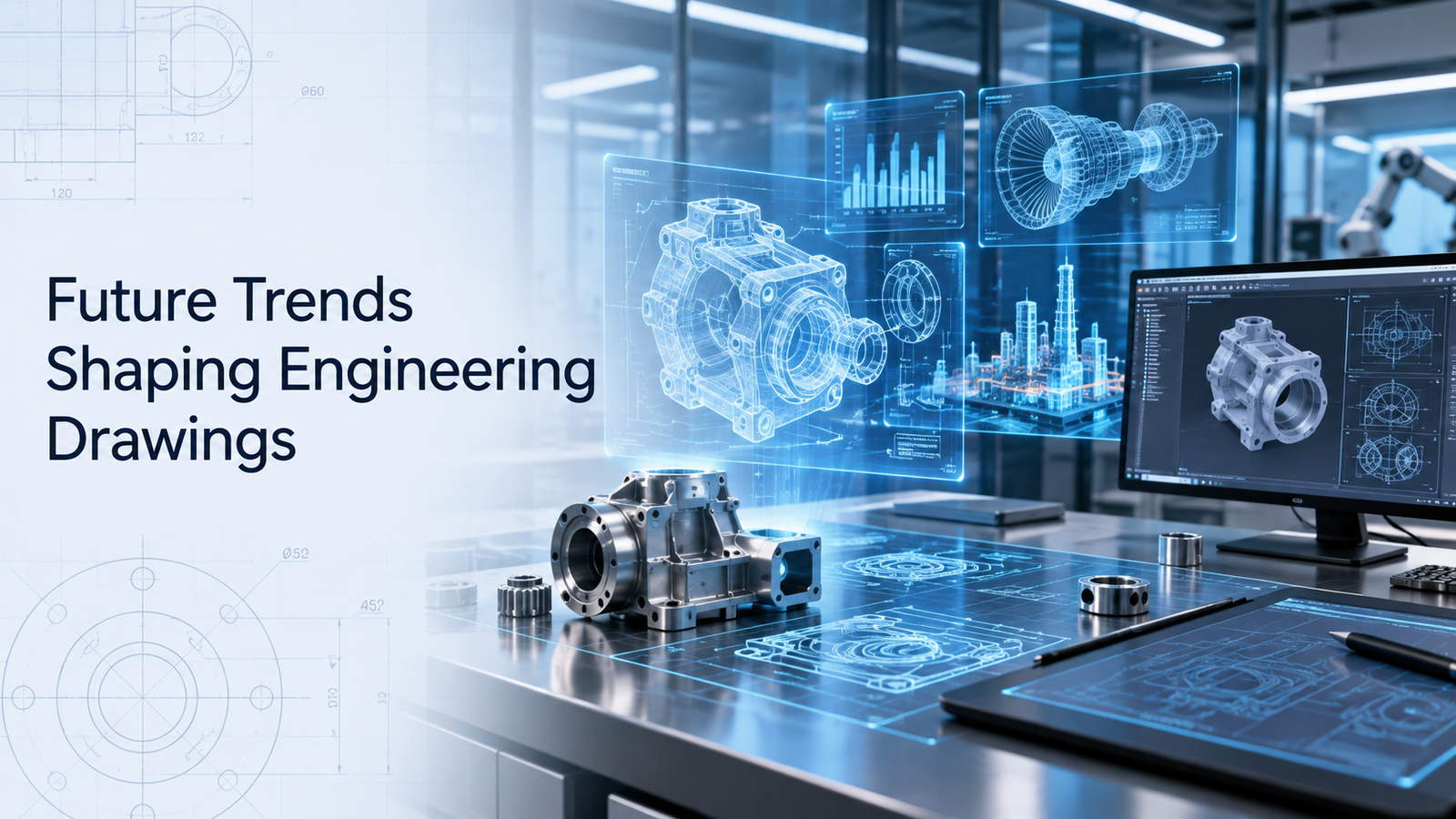
Engineering drawings are changing.
For decades, 2D drawings have been the primary way engineers communicated dimensions, tolerances, materials, surface finishes, assembly information, and inspection requirements. They remain essential in many industries, but modern engineering workflows are increasingly moving toward richer digital product definitions.
The most important engineering drawings trends now include model-based definition, product manufacturing information, digital thread integration, AI-assisted documentation, cloud collaboration, automated inspection, digital twins, augmented reality, and more drawingless manufacturing workflows.
This does not mean that 2D drawings will disappear immediately.
Instead, engineering documentation is becoming more connected, machine-readable, and integrated with CAD, manufacturing, quality, procurement, and lifecycle systems.
This guide explains the key trends shaping the future of engineering drawings and what engineers should prepare for.
Key Technology Trends
1. Model-Based Definition Is Changing Product Documentation
Model-Based Definition (MBD) uses the 3D CAD model as the main source of product definition.
Instead of placing all manufacturing information on a separate 2D drawing, MBD can embed information directly into the model.
This may include:
- Dimensions
- Tolerances
- GD&T
- Surface finish
- Material information
- Notes
- Product Manufacturing Information (PMI)
ISO is actively updating ISO 16792 for digital product definition data practices. The 2026 draft supports both 3D model-only workflows and workflows that combine a 3D model with a 2D drawing.
This is important because engineering organizations are not all moving toward drawingless workflows at the same speed.
2. 3D Models Will Become More Authoritative
Traditional engineering workflows often use:
3D CAD model + 2D drawing
Future workflows increasingly use:
3D annotated model as the primary technical definition
In model-based workflows, the 3D model can become the authoritative source for:
- Design
- Manufacturing
- Inspection
- Assembly
- Service
Siemens describes MBD as a way to create a complete digital product definition using a single 3D model containing product manufacturing information.
This can reduce duplication between the model and drawing.
3. Product Manufacturing Information Will Expand
Product Manufacturing Information, or PMI, includes manufacturing and inspection requirements embedded in the digital model.
PMI can contain:
- Dimensions
- Geometric tolerances
- Surface finish
- Notes
- Material information
- Datums
When PMI is machine-readable, downstream software can use it directly.
For example, PMI may support:
- CAM programming
- Inspection planning
- CMM programming
- Manufacturing simulation
This reduces the need to manually re-enter information from drawings.
4. Digital Thread Will Connect Engineering Data
A digital thread connects product information across different stages of the lifecycle.
Information may flow through:
- Design
- Procurement
- Manufacturing
- Inspection
- Assembly
- Service
NIST's Digital Thread for Manufacturing program focuses on standards and methods needed to support interoperable product-definition data.
A future engineering drawing may therefore be less of a standalone file and more of one view of a connected product data system.
This can improve traceability and reduce duplicate data entry.
5. Drawings Will Become More Machine-Readable
Traditional drawings are primarily designed for humans.
Future product definitions will increasingly be designed for both:
- Humans
- Software
Machine-readable technical information can support:
- Automated manufacturing
- Automated inspection
- Digital quality systems
- Supplier integration
This is important for Industry 4.0 and smart manufacturing.
A dimension may no longer exist only as visible text.
It may also exist as structured data that another engineering system can interpret automatically.
6. Automated GD&T Validation Will Increase
Geometric tolerancing can become complex in large assemblies.
Future CAD tools will increasingly help engineers detect:
- Missing datums
- Incomplete tolerances
- Conflicting specifications
- Invalid GD&T structures
This can reduce drawing-review errors before release.
Automated checking will not replace engineering judgment, but it can identify obvious documentation problems earlier.
7. AI Will Assist Engineering Drawing Creation
Artificial intelligence is beginning to support CAD and engineering documentation tasks.
Future AI tools may help:
- Suggest dimensions
- Detect missing annotations
- Generate drawing views
- Recommend standard notes
- Compare revisions
- Identify documentation inconsistencies
AI may also help convert design intent into draft manufacturing documentation.
However, engineers will still need to validate:
- Functional dimensions
- Tolerances
- Materials
- Safety-critical requirements
Engineering responsibility cannot simply be transferred to an automated tool.
8. AI Will Improve Drawing Review
Drawing reviews are currently time-consuming.
AI-assisted checking may help identify:
- Duplicate dimensions
- Missing dimensions
- BOM mismatches
- Incorrect revision information
- Inconsistent notes
- Tolerance problems
This could reduce routine checking effort.
Engineers could then focus more attention on functional design decisions.
9. Cloud Collaboration Will Replace More File-Based Workflows
Engineering teams increasingly work across:
- Multiple offices
- Suppliers
- International locations
- Remote teams
Cloud-based CAD and PLM systems can make drawings and models easier to share under controlled access.
Benefits may include:
- Central revision control
- Real-time comments
- Supplier access
- Faster approvals
- Reduced duplicate files
This can reduce the risk of suppliers manufacturing from an outdated drawing.
10. Revision Control Will Become More Integrated
Traditional drawing revision control may rely on:
- File names
- PDFs
- Manual release folders
Future systems increasingly connect revision control directly with CAD and PLM.
A design change can potentially update:
- Model
- Drawing
- BOM
- Manufacturing data
- Inspection requirements
This creates stronger configuration control.
11. Digital Twins Will Use Engineering Drawing Data
Digital twins require accurate product definition.
Engineering data can provide the baseline for a digital representation of the physical machine.
The digital twin may combine:
- Geometry
- Product specifications
- Manufacturing data
- Inspection results
- Sensor data
- Service history
This means engineering drawings and MBD data can become part of a much larger lifecycle information system.
12. Inspection Will Become More Automated
Quality inspection is increasingly connected directly to digital product definition.
Model-based characteristics can allow manufacturing requirements to flow from CAD into inspection systems.
In 2026, the DMSC Model-Based Characteristics v1.0 standard received ANSI approval, supporting persistent digital identification of manufacturing and quality characteristics.
This type of standard can help connect CAD requirements with downstream metrology systems.
13. CMM Programming Can Use Digital Product Data
Coordinate Measuring Machines traditionally require inspection programmers to interpret drawings and manually create measurement routines.
Machine-readable PMI can support more automated inspection planning.
This can improve:
- Speed
- Traceability
- Consistency
It also reduces manual interpretation between design and quality.
14. Drawingless Manufacturing Will Expand
Some industries are moving toward workflows in which a fully annotated 3D model replaces the traditional drawing for certain parts.
This is often called:
- Drawingless manufacturing
- Model-based manufacturing
- Model-based enterprise
NIST has documented the industry's long-term transition from drawing-centric communication toward model-based product definition.
However, drawingless manufacturing requires strong control of:
- CAD data
- Standards
- Software compatibility
- Supplier capability
- Revision management
It is not simply a matter of deleting the 2D drawing.
15. 2D Drawings Will Still Remain Important
The move toward MBD does not mean that all 2D drawings will disappear soon.
2D drawings are still valuable for:
- Simple parts
- Supplier communication
- Shop-floor reference
- Installation
- Maintenance
- Legacy processes
Siemens noted in 2026 that many engineering teams are rethinking how 2D drawings are created and maintained rather than assuming they will disappear immediately.
Hybrid workflows will likely remain common.
16. Augmented Reality Could Change Assembly Instructions
Future engineering documentation may be viewed through augmented-reality systems.
Technicians could potentially see:
- Assembly sequence
- Component location
- Fastener information
- Inspection points
directly overlaid on physical equipment.
This can reduce dependence on large printed assembly drawings.
AR may be particularly useful for:
- Complex assembly
- Maintenance
- Training
17. Interactive 3D Work Instructions Will Grow
Instead of reading a static assembly drawing, technicians may increasingly use interactive 3D instructions.
A digital model can show:
- Exploded views
- Installation sequence
- Part identification
- Torque requirements
- Inspection points
This can make technical information easier to understand.
18. Supplier Collaboration Will Become More Digital
Suppliers increasingly receive digital product definitions for quotation and manufacturing.
A connected MBD workflow can support:
- RFQ
- Tooling
- CAM
- Inspection
Siemens describes MBD within the digital thread as supporting procurement, tooling, machining, illustration, and quality processes.
This can reduce repeated translation of design information.
19. Standards Will Continue to Evolve
Engineering documentation standards are changing alongside digital workflows.
ISO/TC 10 reported in June 2026 that it was continuing work on a revision of ISO 16792 for digital product definition data practices.
The current draft is intended to support both:
- 3D model-only methods
- 3D model with 2D drawing methods
This shows that standards organizations are actively supporting the transition toward model-based engineering.
20. Interoperability Will Become Critical
Engineering data must move between:
- CAD
- CAM
- PLM
- CMM
- Supplier systems
Interoperability becomes more important as more information moves into digital models.
Standards such as STEP and QIF are important because they help exchange structured product-definition and quality information between different software platforms.
NIST has emphasized standards-based interoperability as a key requirement for digital manufacturing.
Key Engineering Drawing Trends at a Glance
| Trend | Expected Impact |
|---|---|
| Model-Based Definition | More information inside 3D models |
| Product Manufacturing Information | Machine-readable requirements |
| Digital thread | Connected lifecycle information |
| AI drafting | Faster documentation |
| Automated checking | Fewer drawing errors |
| Cloud collaboration | Better distributed teamwork |
| Integrated revisions | Stronger configuration control |
| Digital twins | Lifecycle connection |
| Automated inspection | Faster quality workflows |
| Drawingless manufacturing | Less dependence on 2D drawings |
| AR instructions | Easier assembly and maintenance |
| Interactive 3D documentation | Better visualization |
| Digital supplier integration | Faster procurement and manufacturing |
| Interoperability standards | Better system-to-system data exchange |
Skills Engineers Will Need
Future engineers should still understand traditional drawing fundamentals.
Important skills include:
- Dimensioning
- Tolerancing
- GD&T
- Datums
- Fits
- Technical drawing standards
But additional skills are becoming valuable:
- Model-Based Definition
- PMI
- PLM
- Digital thread
- Data interoperability
- Automated inspection
- Digital twins
Understanding both traditional drawings and digital product definition will be important during the transition.
Conclusion
The future of engineering drawings is increasingly digital, connected, and machine-readable.
Major engineering drawings trends include Model-Based Definition, Product Manufacturing Information, digital threads, AI-assisted documentation, automated GD&T checking, cloud collaboration, digital twins, model-based inspection, augmented reality, and drawingless manufacturing.
ISO's ongoing 2026 work on the next edition of ISO 16792 reflects this shift toward richer digital product definitions that can support both 3D model-only and hybrid 3D-plus-2D workflows.
Traditional drawing knowledge will remain important because dimensions, tolerances, datums, GD&T, fits, and design intent still need to be communicated correctly.
What is changing is the medium.
Engineering information is moving from isolated 2D documents toward connected digital definitions that can be reused throughout design, manufacturing, quality, assembly, and service.