
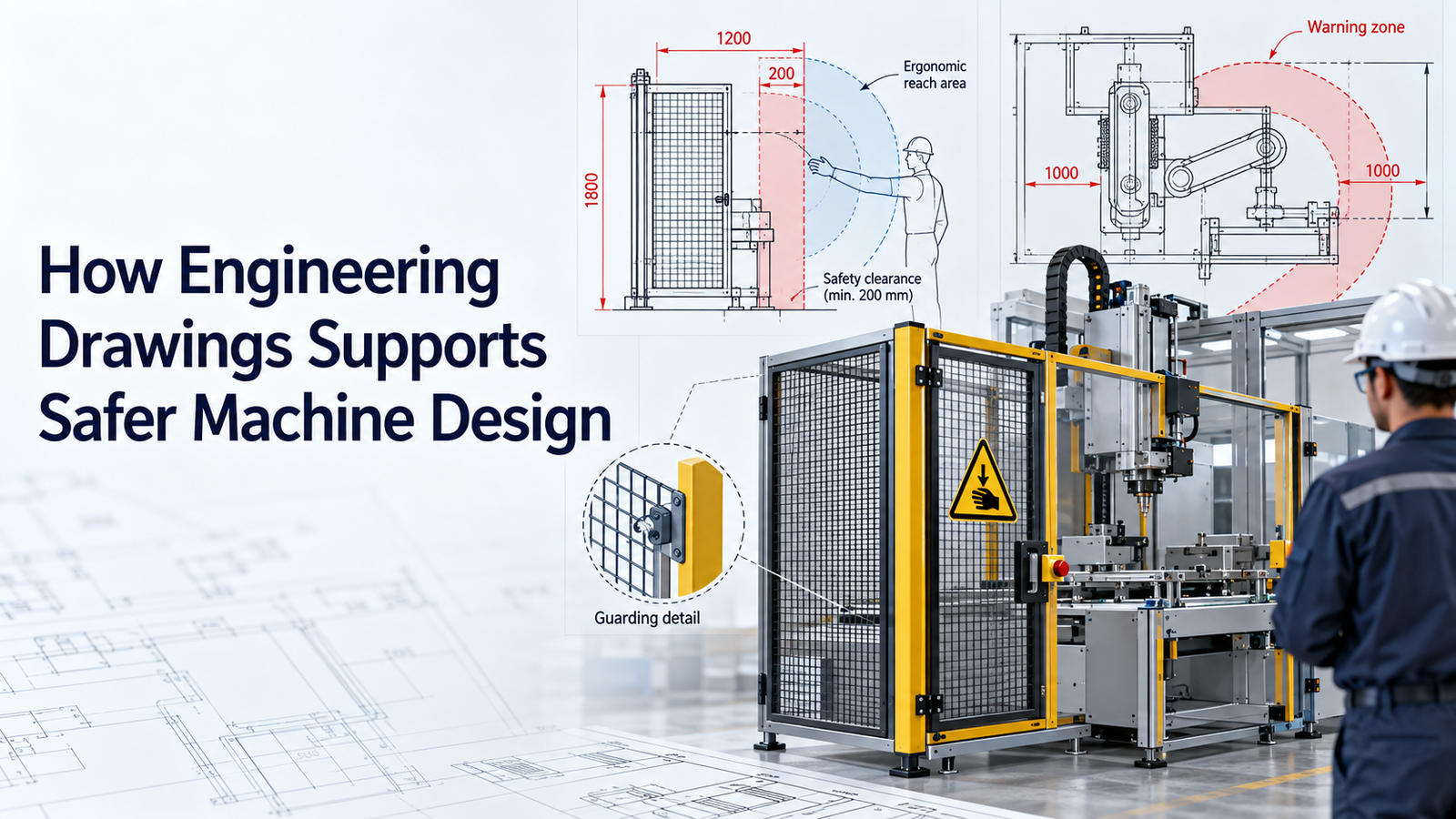
Engineering drawings are not only manufacturing documents. They are also important safety documents.
A well-prepared drawing can communicate guard locations, safety distances, machine clearances, load limits, structural requirements, emergency-stop positions, access zones, lifting points, critical tolerances, and maintenance interfaces.
This is why engineering drawings safety is an important part of modern machine design.
When safety-critical information is missing or unclear, the machine may be manufactured, assembled, installed, or modified differently from the designer's intent. A guard opening may become too large, a support may be installed incorrectly, a critical fastener may be substituted, or maintenance access may expose a worker to hazardous motion.
This guide explains how engineering drawings support safer machine design and how designers can communicate safety requirements more clearly.
Key Steps and Considerations
1. Engineering Drawings Turn Safety Intent Into Technical Requirements
A risk assessment identifies hazards and defines risk-reduction measures.
Engineering drawings convert those decisions into information that manufacturing and assembly teams can actually follow.
Safety-related drawing information may include:
- Guard dimensions
- Guard mounting points
- Safety clearances
- Structural supports
- Mechanical stops
- Access restrictions
- Lifting points
- Service positions
- Critical fasteners
ISO 12100:2010 remains the current published international standard for machinery risk assessment and risk reduction.
The standard emphasizes reducing risk through design before relying only on protective measures or information for use.
A drawing should therefore communicate the physical design features that implement those safety decisions.
2. Show Guarding Clearly
Machine guards should not be represented as optional visual features.
Drawings should clearly define:
- Guard geometry
- Mounting locations
- Fastener requirements
- Openings
- Doors
- Access panels
- Interlock mounting positions
A guard drawing should be detailed enough that the manufactured guard maintains the intended protective function.
If dimensions are left unclear, the final opening or clearance may differ from the safety assessment.
3. Document Safety Distances
Safety distances should not be estimated by installers.
ISO 13857:2019 remains current and establishes safety distances intended to prevent upper and lower limbs from reaching machinery hazard zones through or around protective structures.
A replacement edition is under development, so organizations should always verify the edition applicable to their project.
Engineering drawings can document:
- Guard height
- Distance from guard to hazard
- Opening size
- Access gaps
- Clearance below fencing
This helps make the safety concept repeatable during manufacturing and installation.
4. Show the Full Hazardous Motion Envelope
A machine may appear safe in one position but create a hazard during movement.
Drawings or layout documents should consider:
- Maximum travel
- Minimum travel
- Rotating envelopes
- Robot or actuator reach
- Moving-table positions
- Maintenance positions
This is important when defining:
- Fencing
- Guard clearance
- Walkways
- Maintenance access
The complete motion envelope should be reviewed, not only the normal parked position.
5. Define Mechanical Stops and Travel Limits
Mechanical stops can help prevent movement beyond the intended range.
A drawing should define:
- Stop location
- Stop material
- Fastener size
- Contact surface
- Required strength
If a mechanical stop may absorb significant kinetic energy, its design should be verified accordingly.
Do not show a critical stop as an approximate feature without dimensions or specifications.
6. Communicate Emergency-Stop Locations
ISO 13850:2015 remains the current published international standard for emergency-stop function principles, while a new edition is under development.
Machine-layout drawings can help define where emergency-stop devices are physically located.
This is important because access should not be blocked by:
- Guards
- Cabinets
- Material racks
- Machine frames
- Operator platforms
The mechanical layout should support quick access to emergency controls from relevant working positions.
7. Show Safe Access Zones
Drawings should consider how operators and technicians approach the machine.
Useful information may include:
- Walkways
- Service clearances
- Door swing areas
- Operator standing zones
- Maintenance zones
This is especially important for machines installed close to:
- Walls
- Other machines
- Columns
- Conveyors
A machine that is safe in isolation may become difficult or hazardous to service if site clearances are not defined.
8. Mark Stored-Energy Components
Stored mechanical or fluid energy may remain after the machine is stopped.
Examples include:
- Pneumatic cylinders
- Hydraulic accumulators
- Springs
- Elevated loads
- Counterweights
Drawings can help identify:
- Mechanical locking positions
- Support points
- Pressure-release components
- Blocking locations
This makes maintenance planning clearer and reduces the risk of unexpected movement.
9. Define Structural Requirements Clearly
Safety depends on structural integrity.
Drawings should specify the requirements needed to achieve the intended strength.
This may include:
- Material grade
- Plate thickness
- Weld size
- Fastener grade
- Anchor size
- Critical dimensions
Vague structural drawings can lead to substitutions that reduce load capacity.
Safety-critical structural elements should be clearly controlled.
10. Use Correct Tolerances on Safety-Critical Features
Some safety functions depend on geometry.
Examples include:
- Guard openings
- Mechanical stops
- Retaining features
- Locking-pin holes
- Brake mounting interfaces
If tolerances are too wide, the final feature may not provide the intended protection.
ISO 1101:2017 remains current and provides the ISO framework for geometrical tolerancing.
Use dimensional or geometric tolerances where safety-related fit, location, or orientation matters.
11. Use Datums for Repeatable Safety Geometry
Datums can help control safety-critical positions consistently.
For example:
- Guard bracket location
- Stop position
- Access opening
- Interlock mounting feature
should be referenced from stable functional surfaces.
A poor datum strategy can create variation even when individual dimensions are technically within tolerance.
12. Detail Interlock Mounting Features
Interlocked guards depend on correct mechanical installation.
Drawings should define:
- Mounting holes
- Bracket locations
- Alignment
- Door position
- Adjustment range
A misaligned actuator or switch may create reliability problems or prevent the safety function from operating as intended.
Mechanical accuracy is therefore part of the overall safety design.
13. Show Safe Lifting Points
Heavy machine components may require lifting during:
- Assembly
- Installation
- Maintenance
- Relocation
Drawings should identify designed lifting points where applicable.
Information may include:
- Lifting-eye location
- Required hardware
- Load direction
- Component mass
Improvised lifting from unsuitable brackets can create structural failure or dropped loads.
14. Document Machine Mass and Center of Gravity
Large machines and subassemblies can be difficult to move safely.
General arrangement or installation drawings may include:
- Total mass
- Center-of-gravity information
- Lifting locations
- Support points
This is especially useful for transport and installation planning.
15. Show Maintenance Access
Maintenance drawings should show how technicians reach critical components.
Examples include:
- Motor removal clearance
- Bearing access
- Filter access
- Guard removal direction
- Tool clearance
Poor access can encourage unsafe shortcuts.
Designing and documenting service space makes safer maintenance more practical.
16. Use Section Views for Hidden Safety Features
Some safety-related components are located inside assemblies.
Examples include:
- Retaining rings
- Shaft shoulders
- Internal stops
- Locking pins
- Brakes
ISO 128-3:2022 defines conventions for views, sections, and cuts in technical product documentation.
A section view can make these hidden features much easier to verify during manufacturing and maintenance.
17. Add Safety-Related Assembly Notes Carefully
Drawings can include assembly instructions where necessary.
Examples include:
- Install retaining ring before operation
- Tighten safety-critical fasteners to approved specification
- Verify mechanical stop before commissioning
- Install guard before operation
Notes should be specific, technically meaningful, and consistent with company procedures.
Avoid vague instructions such as “make safe.”
18. Use BOMs to Control Safety-Critical Components
The Bill of Materials should clearly identify critical purchased components.
Examples may include:
- Guard switches
- Brakes
- Retaining hardware
- Special fasteners
- Approved structural components
If an incorrect substitute is installed, the safety performance may change.
Part numbers and specifications should therefore be controlled.
19. Prevent Unauthorized Substitution
Drawings can identify where substitutions are not acceptable without engineering review.
For example, a standard-looking bolt may have a required strength grade.
A similar-looking retaining component may not have the same load capacity.
Critical requirements should be explicit enough that procurement and maintenance teams understand when engineering approval is required.
20. Keep Safety Drawings Under Revision Control
Safety-related drawings must remain current.
If a guard, actuator, platform, or machine layout changes, the drawings should be updated.
Revision control should record:
- Revision number
- Date
- Change description
- Approval
An obsolete drawing can reintroduce a hazard that was already corrected.
21. Maintain Accurate As-Built Drawings
The machine installed on site should match the controlled documentation.
If approved modifications are made during commissioning, update the drawings.
Typical changes may include:
- Guard position
- Sensor bracket
- Access door
- Service platform
- Mechanical stop
As-built documentation supports future maintenance and risk assessment.
22. Use Drawings During Safety Validation
Before final release, drawings can be used as part of the safety validation process.
Verify:
- Guard dimensions
- Safety distances
- Mechanical stops
- Access zones
- Critical fasteners
- Emergency-stop positions
- Service clearances
Compare the actual machine against the approved design documentation.
This helps identify manufacturing or installation deviations.
Engineering Drawing Safety Checklist
| Drawing Area | Safety Question |
|---|---|
| Guarding | Is geometry fully defined? |
| Safety distance | Is hazard clearance documented? |
| Motion envelope | Is full travel considered? |
| Mechanical stop | Is location and strength defined? |
| Emergency stop | Is access clear? |
| Stored energy | Are support or lock points identified? |
| Structure | Are critical materials and fasteners specified? |
| Tolerances | Are safety-critical features controlled? |
| Maintenance | Is safe access provided? |
| Lifting | Are approved lifting points shown? |
| BOM | Are critical components controlled? |
| Revision | Is the latest approved design in use? |
Common Safety-Related Drawing Mistakes
Avoid these mistakes:
- Showing guards without dimensions
- Estimating safety distances
- Ignoring the full motion envelope
- Leaving critical stop locations undefined
- Blocking emergency-stop access
- Failing to identify stored-energy support points
- Omitting fastener grades on critical joints
- Using loose tolerances on safety-critical features
- Missing maintenance clearances
- Allowing unauthorized component substitutions
- Failing to update as-built drawings
- Using outdated revisions during maintenance
Good safety documentation reduces ambiguity and helps ensure that safety measures survive manufacturing, installation, and future modification.
Conclusion
Engineering drawings are an important part of safe machine design.
A strong engineering drawings safety approach ensures that risk-reduction measures are communicated clearly from engineering to manufacturing, assembly, installation, inspection, and maintenance teams.
Guard dimensions, safety distances, hazardous motion envelopes, mechanical stops, structural requirements, access zones, lifting points, safety-critical tolerances, and revision control all contribute to safer equipment.
ISO 12100:2010 remains the current published framework for machinery risk assessment and risk reduction. ISO 13857:2019 remains current for safety distances, ISO 13850:2015 remains current for emergency-stop principles, ISO 128-1:2020 remains current for general technical drawing principles, and ISO 1101:2017 remains current for geometrical tolerancing.
When safety decisions are translated into precise and controlled engineering drawings, they become easier to manufacture, inspect, validate, and maintain throughout the machine lifecycle.