
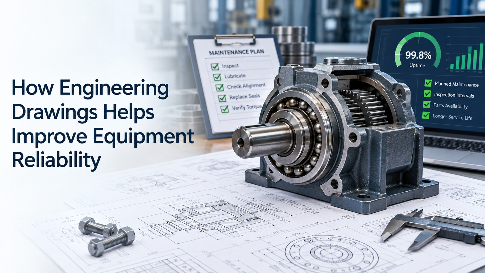
Engineering drawings do much more than help manufacture a machine.
They also play an important role throughout the equipment lifecycle. Maintenance teams use drawings to identify parts, understand assemblies, verify dimensions, check fits, locate lubrication points, diagnose failures, order replacements, and restore equipment to the correct condition after repair.
This is why engineering drawings maintenance practices are closely connected with equipment reliability.
A machine may be designed correctly, but if the maintenance team works from outdated, incomplete, or unclear drawings, problems can develop during repair and replacement. Bearings may be installed with the wrong fit, shafts may be machined incorrectly, alignment may be lost, or replacement parts may not match the original design.
This guide explains how engineering drawings improve equipment reliability and how maintenance teams can use them more effectively.
Key Reliability Practices
1. Drawings Preserve the Original Design Intent
A machine can operate for many years.
During that time:
- Components are replaced
- Parts are modified
- Suppliers change
- Maintenance personnel change
- Equipment may be relocated
Without reliable drawings, the original design intent can gradually be lost.
A controlled drawing records important information such as:
- Dimensions
- Tolerances
- Fits
- Materials
- Surface requirements
- Part numbers
- Assembly relationships
This allows future maintenance work to restore the machine to its intended condition rather than relying on guesswork.
2. Accurate Dimensions Help Prevent Incorrect Replacement Parts
Replacement parts must match the functional dimensions of the original design.
Important dimensions may include:
- Shaft diameter
- Bearing housing bore
- Hole pattern
- Keyway size
- Mounting distance
- Guide spacing
If a replacement part is made using an approximate measurement from a worn component, the error may be repeated or increased.
A controlled drawing provides the nominal dimensions and tolerances required for correct replacement.
This improves interchangeability and reduces repeated failures.
3. Tolerances Help Maintain Functional Performance
A dimension alone is not always enough.
A drawing also defines the allowable variation.
ISO 129-1:2018 remains the current published ISO standard for presenting dimensions and associated tolerances, although a replacement edition is under development.
Correct tolerances are important for maintenance because they help determine whether:
- A worn shaft is still acceptable
- A housing bore is within specification
- A replacement component can be reused
- A repair requires machining
This turns maintenance decisions into measurable engineering decisions rather than visual judgment.
4. Fits Are Critical for Bearings and Shafts
Bearing reliability depends strongly on correct shaft and housing fits.
If a fit is too loose:
- The bearing ring may creep
- Fretting may occur
- Alignment may change
If a fit is too tight:
- Internal bearing clearance may reduce
- Heat may increase
- Installation may become difficult
Engineering drawings should clearly communicate the required shaft and housing dimensions.
Maintenance teams can then inspect repaired or replacement surfaces before reassembly.
5. Drawings Support Accurate Alignment
Alignment problems can cause repeated failures in:
- Bearings
- Couplings
- Belts
- Gears
- Linear guides
Drawings can define the reference surfaces and dimensions needed for correct installation.
Examples include:
- Shaft center distance
- Guide rail spacing
- Motor mounting location
- Datum surfaces
If these relationships are not preserved during maintenance, the machine may return to service with hidden misalignment.
6. GD&T Helps Control Critical Geometry
Geometric Dimensioning and Tolerancing helps define how surfaces and features relate to each other.
ISO 1101:2017 remains current and defines the ISO symbol language for geometric tolerancing.
Useful controls can include:
- Flatness
- Parallelism
- Perpendicularity
- Position
- Runout
For maintenance and reliability, these controls help answer questions such as:
- Is the mounting face still flat enough?
- Is the shaft running true?
- Is the bearing bore aligned?
- Are replacement holes in the correct position?
GD&T gives maintenance and inspection teams more complete information than simple linear dimensions alone.
7. Section Views Help Maintenance Teams Understand Assemblies
Internal machine features are often difficult to understand from external views.
Section views can show:
- Bearing arrangement
- Spacer sequence
- Seal location
- Shaft shoulders
- Internal fasteners
- Lubrication paths
ISO 128-3:2022 specifies general principles for presenting views, sections, and cuts in technical drawings.
A clear section drawing helps maintenance personnel disassemble and rebuild complex assemblies correctly.
8. Assembly Drawings Reduce Reassembly Errors
Assembly drawings show how multiple components fit together.
They can identify:
- Component orientation
- Fastener locations
- Spacer positions
- Bearing direction
- Seal arrangement
- Item numbers
This becomes especially important when a machine is dismantled during major maintenance.
Without a reliable assembly drawing, a component may be installed in the wrong orientation or a spacer may be omitted.
Such mistakes can create premature failures even if each individual component is correct.
9. BOMs Improve Spare-Part Identification
A Bill of Materials helps maintenance teams identify the correct parts.
Typical BOM data may include:
- Item number
- Part number
- Description
- Quantity
- Manufacturer reference
This helps prevent incorrect procurement.
For example, two bearings may look similar but have different:
- Internal clearance
- Seal type
- Precision class
- Load capacity
Using the drawing and BOM together reduces the risk of installing an unsuitable substitute.
10. Drawings Help Standardize Spare Parts
Engineering drawings can reveal where common components are used across equipment.
This can support spare-part standardization.
Benefits include:
- Lower inventory
- Faster replacement
- Easier procurement
- Better maintenance training
Common parts may include:
- Bearings
- Fasteners
- Couplings
- Sensors
- Seals
However, standardization should only be used where the specification actually matches the application.
11. Maintenance Drawings Can Identify Lubrication Points
Lubrication is essential for many mechanical systems.
Drawings can identify:
- Grease points
- Lubrication channels
- Oil level locations
- Lubricant type
- Access points
This helps technicians follow the correct maintenance procedure.
If lubrication points are not documented, some components may be missed during routine service.
12. Drawings Improve Inspection Planning
Maintenance inspections can use drawing tolerances as acceptance criteria.
Examples include checking:
- Shaft wear
- Bore diameter
- Flatness
- Runout
- Alignment
This helps distinguish between:
- Acceptable wear
- Repairable damage
- Required replacement
Inspection becomes more consistent when the team has a defined drawing specification.
13. Drawings Support Root-Cause Troubleshooting
When failures repeat, drawings help engineers investigate the mechanical relationships around the failed component.
For example, repeated bearing failure may be linked to:
- Incorrect shaft fit
- Housing misalignment
- Wrong spacer length
- Shaft runout
A drawing allows the maintenance team to compare the actual machine against the intended geometry.
This can reveal whether the problem comes from the component itself or from the surrounding design condition.
14. As-Built Drawings Are Important
Machines often change after installation.
Modifications may include:
- New sensors
- Replacement motors
- Guard changes
- Bracket changes
- Revised pipe routes
If drawings are not updated, the documentation no longer represents the machine.
This creates risk during future maintenance.
After approved modifications, drawings should be updated to reflect the as-built condition.
15. Revision Control Prevents Maintenance Errors
Technicians should always use the latest approved drawing.
Revision control should identify:
- Revision number
- Change description
- Date
- Approval
If an old drawing remains in circulation, a maintenance team may manufacture or install a part that no longer matches the machine.
Controlled document systems reduce this risk.
16. Drawings Reduce Dependence on Individual Knowledge
Experienced technicians often know a machine very well.
But that knowledge can be lost when people:
- Retire
- Transfer
- Change roles
Good drawings preserve technical information independently of one person.
This improves long-term maintainability and reduces reliance on tribal knowledge.
17. Installation Drawings Help During Equipment Relocation
Machines may need to be moved or reinstalled.
Installation drawings can define:
- Anchor locations
- Machine orientation
- Base dimensions
- Service clearances
- Interface points
This helps prevent misalignment or incorrect installation after relocation.
A machine that is reinstalled incorrectly may develop vibration or alignment problems even if the mechanical components are undamaged.
18. Drawings Help Verify Repairs Before Restart
After major repair, use drawings as a verification checklist.
Confirm:
- Correct part numbers
- Correct orientation
- Required dimensions
- Critical fits
- Alignment references
- Fastener locations
This reduces the risk of restarting the machine with an incorrect assembly.
19. Update Drawings After Permanent Maintenance Modifications
Sometimes maintenance teams create successful permanent improvements.
Examples include:
- Stronger bracket
- Improved guard
- New lubrication point
- Revised spacer
If the change is approved as permanent, update the drawing.
Otherwise, the next maintenance team may unknowingly return the machine to the old design.
20. Build a Maintenance Drawing Package
For critical equipment, create a controlled maintenance drawing package.
Useful documents may include:
- General arrangement drawing
- Assembly drawings
- Critical part drawings
- BOM
- Installation drawing
- Lubrication diagram
This allows maintenance teams to quickly access the technical information needed during breakdowns or planned shutdowns.
Engineering Drawing Reliability Checklist
| Reliability Area | Drawing Information Needed |
|---|---|
| Replacement parts | Dimensions and tolerances |
| Bearings | Fits and seating dimensions |
| Alignment | Datums and center distances |
| Inspection | Acceptance tolerances |
| Assembly | Sections and orientation |
| Spare parts | BOM and part numbers |
| Lubrication | Service locations |
| Troubleshooting | Geometry and interfaces |
| Modification | Updated as-built drawing |
| Relocation | Installation references |
| Repair validation | Latest approved revision |
Common Drawing-Related Maintenance Mistakes
Avoid these mistakes:
- Using outdated drawings
- Measuring worn parts instead of checking nominal dimensions
- Ignoring fits and tolerances
- Installing visually similar spare parts
- Reassembling without section or assembly drawings
- Making permanent modifications without updating documentation
- Keeping uncontrolled drawing copies on the shop floor
- Ignoring inspection requirements after repair
Good engineering drawings reduce uncertainty during maintenance and help preserve machine performance over time.
Conclusion
Engineering drawings are an important reliability tool.
Good engineering drawings maintenance practices help teams replace components correctly, maintain fits and alignment, identify spare parts, inspect wear, troubleshoot recurring failures, and preserve the original design intent.
Standards such as ISO 128-1, ISO 128-3, ISO 129-1, and ISO 1101 provide consistent technical drawing conventions for representation, dimensions, tolerances, and geometry.
A reliable machine depends not only on good components but also on accurate technical information throughout its lifecycle.
When drawings are maintained, revised, and used actively during service work, they help reduce maintenance errors, improve repair quality, and extend equipment life.