
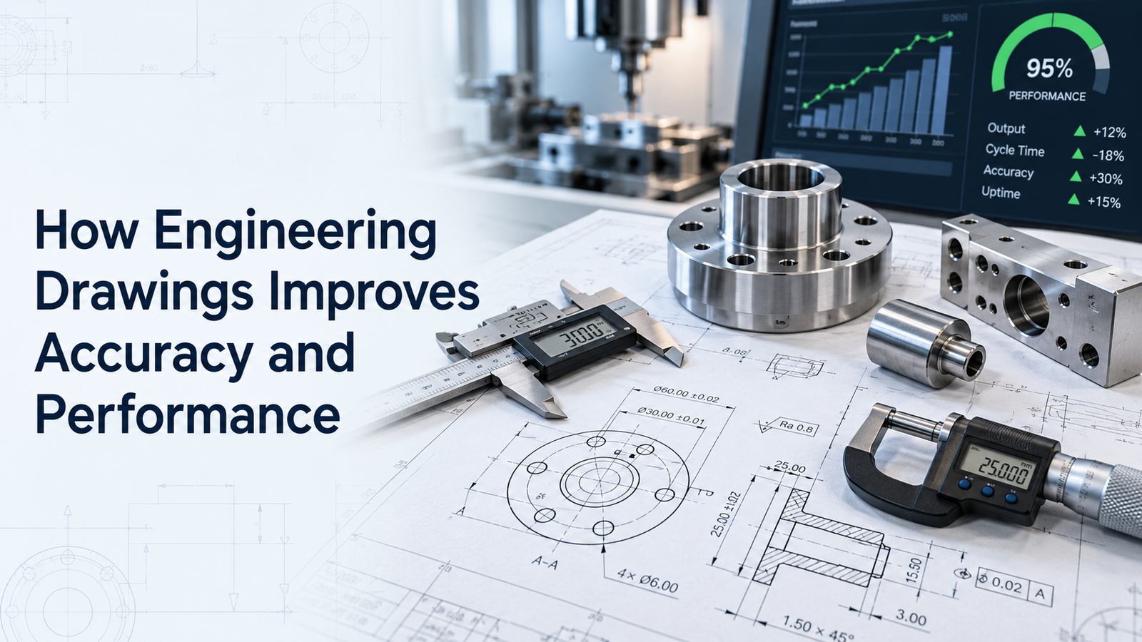
Engineering drawings play a major role in how accurately a product is manufactured, assembled, inspected, installed, and maintained.
A strong drawing does more than describe shape. It communicates the exact design intent needed to control dimensions, tolerances, datums, fits, geometric relationships, materials, and assembly interfaces.
This is why engineering drawings efficiency is directly connected with machine accuracy and performance.
When drawings are clear and function-focused, manufacturing teams can produce parts more consistently, inspectors can verify critical features more effectively, and assembly teams can maintain alignment and fit across repeated builds.
This guide explains how engineering drawings improve accuracy, reduce variation, support better performance, and make engineering work more efficient.
Performance Improvement Steps
1. Engineering Drawings Convert Design Intent Into Measurable Requirements
A CAD model shows geometry, but manufacturing requires measurable instructions.
Engineering drawings define:
- Dimensions
- Tolerances
- Datums
- Fits
- Geometric controls
- Materials
- Surface requirements
- Notes
ISO 128-1:2020 provides general rules for technical drawings and remains current after being reviewed and confirmed in 2026.
A good drawing allows production and inspection teams to understand exactly which characteristics matter.
This reduces interpretation differences between engineering and manufacturing.
2. Functional Dimensioning Improves Accuracy
Not every dimension has the same importance.
Functional dimensions directly affect:
- Alignment
- Clearance
- Movement
- Fit
- Position
For example, the distance between two bearing centers may be critical to shaft alignment, while an external cover dimension may allow much wider variation.
Good drawings prioritize functional dimensions.
This helps manufacturing teams focus precision where it provides real performance value.
3. Datums Create Consistent References
Datums provide reference features for manufacturing and inspection.
Typical datums may be:
- Mounting faces
- Shaft axes
- Locating holes
- Precision edges
- Bearing bores
A well-planned datum system ensures that critical features are measured from the same functional references used during assembly.
This improves consistency.
Without clear datums, different manufacturers or inspectors may use different reference points and obtain different results.
4. Correct Tolerances Control Variation
Every manufactured feature varies.
Tolerances define how much variation is acceptable.
ISO 129-1:2018 remains the currently published ISO standard for presenting dimensions and associated tolerances, although a future replacement edition is under development.
Correct tolerances help balance:
- Performance
- Manufacturing capability
- Inspection effort
- Cost
Tolerances that are too wide may reduce accuracy.
Tolerances that are unnecessarily tight may increase cost without improving machine performance.
The objective is to specify the tolerance required by the function.
5. GD&T Improves Geometric Accuracy
Simple dimensional tolerances do not always describe geometric relationships clearly.
Geometric Dimensioning and Tolerancing can control:
- Flatness
- Straightness
- Parallelism
- Perpendicularity
- Position
- Runout
ISO 1101:2017 defines the ISO symbol language and interpretation rules for geometrical tolerancing and remains current.
For example, two mounting holes may have correct coordinate dimensions but still create assembly problems if their true position relative to the locating datums is not adequately controlled.
GD&T can define that relationship more directly.
6. Better Datum Structures Improve Assembly Performance
Assembly accuracy depends on repeatable positioning.
A component may be dimensionally correct but still assemble poorly if its references do not match the way it is located in the machine.
Good drawings align the datum system with:
- Mounting sequence
- Functional contacts
- Locating features
This helps prevent:
- Misalignment
- Uneven loading
- Assembly variation
It is particularly important for:
- Bearing housings
- Linear guide supports
- Gear assemblies
- Precision fixtures
7. Fit Specifications Improve Mechanical Performance
Mechanical interfaces often require controlled fits.
Examples include:
- Shaft and bearing
- Pin and hole
- Bushing and housing
- Coupling and shaft
Depending on the function, the design may require:
- Clearance fit
- Transition fit
- Interference fit
A wrong fit can cause:
- Excessive play
- Heat
- Fretting
- Difficult assembly
- Reduced bearing life
Accurate engineering drawings ensure the required fit is communicated to manufacturing and inspection teams.
8. Drawing Accuracy Supports Better Bearing Installation
Bearings depend on correct:
- Shaft diameter
- Housing bore
- Shoulder location
- Alignment
- Surface condition
If these features vary beyond acceptable limits, bearing performance may be affected even when the bearing itself is correct.
Good drawings allow critical bearing interfaces to be manufactured and inspected consistently.
This improves reliability, vibration performance, and service life.
9. Drawings Improve Linear Guide Alignment
Linear guides require good mounting geometry.
Important factors may include:
- Rail spacing
- Mounting-face straightness
- Parallelism
- Hole position
Poor guide alignment can increase:
- Friction
- Internal loading
- Wear
- Position error
Drawings that clearly define critical reference surfaces and geometric relationships help assembly teams achieve more consistent guide installation.
10. Tolerance Stack-Up Analysis Improves Assembly Accuracy
Several acceptable part variations can combine into an unacceptable assembly condition.
This is known as tolerance stack-up.
Typical examples include:
- Shaft assemblies
- Spacer stacks
- Bearing positions
- Sensor gaps
- Gear center distance
Engineers should review the complete tolerance chain rather than evaluating individual parts independently.
Where necessary, dimension critical features from common datums to reduce accumulated variation.
11. Surface Requirements Can Affect Performance
Surface finish can influence:
- Friction
- Sealing
- Wear
- Bearing fit
- Sliding motion
Not every surface needs the same finish.
Good drawings specify surface requirements only where they affect function.
This maintains performance while avoiding unnecessary machining cost.
12. Drawings Improve Manufacturing Repeatability
Production performance depends on repeatability.
If every operator interprets a part differently, variation increases.
A controlled engineering drawing provides a common technical definition.
This is especially valuable when parts are produced:
- At different times
- By different operators
- By multiple suppliers
Consistent documentation supports consistent output.
13. Clear Section Views Reduce Manufacturing Errors
Internal features can be difficult to interpret using external views alone.
Section views help explain:
- Bearing seats
- Counterbores
- Internal shoulders
- Grooves
- Recesses
Clear representation reduces the chance of machining the wrong depth, orientation, or internal geometry.
14. Drawings Improve Inspection Efficiency
A well-designed drawing helps inspectors know:
- What to measure
- Which datums to use
- Which tolerances matter
- Which geometry is critical
This makes inspection more focused.
Instead of checking every dimension with equal importance, inspection can prioritize performance-critical features.
A drawing should also specify requirements that can realistically be measured with available inspection methods.
15. Assembly Drawings Improve Build Consistency
Assembly drawings communicate:
- Part location
- Orientation
- Fasteners
- Spacers
- Sequence
- Item numbers
This reduces variation between technicians.
Consistent assembly improves machine performance because parts are located and installed in the intended arrangement every time.
16. BOM Accuracy Improves Build Efficiency
A Bill of Materials should match the assembly drawing.
Correct BOM information prevents:
- Wrong bearing selection
- Incorrect fasteners
- Missing components
- Wrong quantities
A good BOM reduces production interruptions and procurement errors.
This improves overall engineering and assembly efficiency.
17. Revision Control Protects Performance
Engineering changes are common.
A modified hole pattern, bearing fit, or mounting thickness may improve performance, but the benefit is lost if production continues using the old drawing.
Good revision control should identify:
- Revision number
- Date
- Change
- Approval
Manufacturing, inspection, and suppliers should use the same approved revision.
This prevents the accidental reintroduction of old problems.
18. Drawings Improve Installation Accuracy
Machine installation can affect equipment performance.
Installation drawings can define:
- Anchor locations
- Equipment orientation
- Leveling references
- Interface dimensions
- Clearances
Incorrect installation can create alignment, vibration, or access problems.
Clear installation drawings help ensure that the machine is positioned as intended by the design team.
19. Standard Drawing Practices Improve Engineering Productivity
Consistent drawing standards reduce the time required to interpret technical information.
Standardize:
- Title blocks
- Notes
- Symbols
- Dimension styles
- BOM format
- Revision format
This makes drawings easier to review and reduces avoidable questions.
Engineering teams can spend more time solving design problems and less time interpreting inconsistent documentation.
20. Drawings Create a Feedback Loop for Optimization
Production and inspection data can be used to improve drawings.
For example, repeated manufacturing difficulty may show that:
- A tolerance is unnecessarily tight
- A datum is difficult to use
- A feature is difficult to inspect
Engineering can then revise the drawing.
This creates a continuous improvement cycle:
- Design
- Manufacture
- Inspect
- Learn
- Optimize
Drawing optimization therefore improves both product performance and engineering efficiency.
Engineering Drawing Performance Checklist
| Drawing Area | Performance Benefit |
|---|---|
| Functional dimensions | Better fit and alignment |
| Datums | Consistent reference system |
| Tolerances | Controlled variation |
| GD&T | Better geometric accuracy |
| Fits | Reliable mechanical interfaces |
| Stack-up | Improved assembly accuracy |
| Surface finish | Better functional surfaces |
| Sections | Fewer interpretation errors |
| Inspection | Faster quality verification |
| Assembly drawing | Repeatable builds |
| BOM | Correct components |
| Revision control | Consistent latest design |
| Installation drawing | Better site alignment |
| Standardization | Faster engineering workflow |
Common Drawing Optimization Mistakes
Avoid these mistakes:
- Applying equal precision to every dimension
- Choosing datums unrelated to function
- Using unnecessarily tight tolerances
- Adding GD&T without a clear purpose
- Ignoring tolerance stack-up
- Specifying surface finish everywhere
- Creating drawings that are difficult to inspect
- Allowing BOM and drawing data to differ
- Weak revision control
- Failing to update drawings using manufacturing feedback
The most effective drawing is not necessarily the most complicated one. It is the drawing that controls the features that matter to performance while keeping manufacturing and inspection practical.
Conclusion
Good engineering drawings improve both product accuracy and engineering efficiency.
A strong engineering drawings efficiency approach uses functional dimensions, logical datums, appropriate tolerances, GD&T, fit control, tolerance-stack analysis, clear assembly information, inspection planning, and revision control.
Current standards such as ISO 128-1:2020 provide general technical-drawing rules, while ISO 129-1:2018 covers the presentation of dimensions and tolerances and ISO 1101:2017 provides the framework for geometric tolerancing.
When drawing requirements are directly connected to function, manufacturers can control important features more consistently and avoid wasting precision on noncritical areas.
The result is better alignment, improved assembly repeatability, lower variation, more effective inspection, and stronger machine performance.