
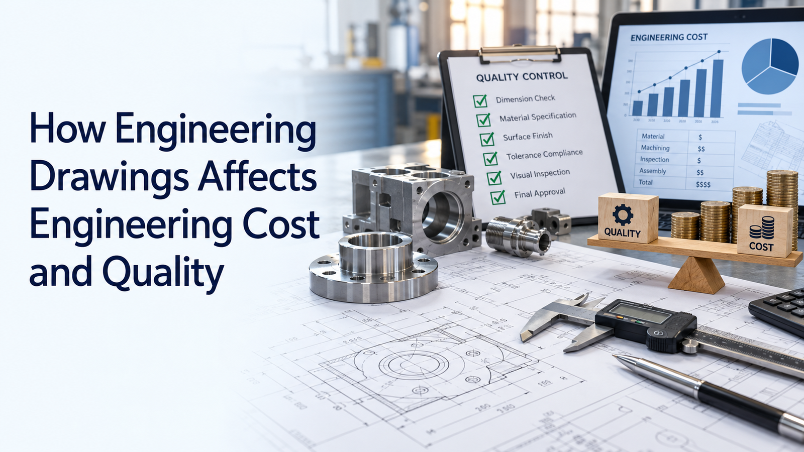
Engineering drawings directly influence both project cost and product quality.
A drawing is not just a technical record. It tells suppliers what to manufacture, inspectors what to measure, assemblers how components fit together, and procurement teams what must be purchased. If the drawing is unclear or unnecessarily complex, cost can rise quickly through extra machining, inspection, supplier questions, rework, scrap, delayed delivery, and assembly problems.
This is why understanding engineering drawings cost is important for engineering and procurement teams.
A well-prepared drawing can reduce ambiguity, improve supplier quotations, control the right features, and avoid paying for precision that does not improve performance.
ASME notes that standardized dimensioning and tolerancing helps communicate form, fit, function, and interchangeability while reducing manufacturing guesswork, which can improve quality, lower cost, and shorten delivery time.
This guide explains how engineering drawings affect cost and quality throughout the product lifecycle.
Key Cost Factors
1. Drawing Quality Affects Supplier Quotations
Suppliers price the requirements shown on the drawing.
If a drawing includes:
- Very tight tolerances
- Complex geometry
- Special finishes
- Difficult materials
- Unusual inspection requirements
the supplier must include those requirements in the quotation.
Unclear drawings can also increase price because the supplier may add contingency for uncertainty.
A clear drawing helps suppliers understand:
- What is critical
- What manufacturing process may be needed
- What inspection effort is required
Better information usually creates more comparable and reliable quotations.
2. Tight Tolerances Can Increase Cost Significantly
Tolerance is one of the biggest drawing-related cost drivers.
Very tight tolerances may require:
- Precision CNC machines
- Grinding
- Additional setups
- Temperature-controlled inspection
- Slower machining
- More measurement
- Higher rejection rates
Not every dimension needs high precision.
For example, a bearing seat may require tight dimensional control, while a protective cover may not.
The best approach is to apply tighter tolerances only where they support function.
3. General Tolerances Reduce Drawing Complexity
Not every noncritical dimension requires an individual tolerance.
General tolerance systems can simplify drawings and reduce unnecessary specification.
This helps engineers focus attention on critical features.
However, general tolerances must still match:
- Manufacturing process
- Material
- Part size
- Functional need
Using an appropriate general tolerance can reduce drawing clutter while keeping manufacturing requirements clear.
4. GD&T Can Improve Quality and Reduce Cost
Geometric Dimensioning and Tolerancing can improve engineering communication when used correctly.
ASME Y14.5-2018 remains in effect and establishes standardized rules for dimensioning and tolerancing.
GD&T can control:
- Flatness
- Straightness
- Parallelism
- Perpendicularity
- Position
- Runout
The major advantage is that it can describe functional relationships more directly than many conventional plus/minus dimensions.
ASME specifically notes that GD&T supports form, fit, function, and interchangeability and can reduce manufacturing guesswork.
Correct GD&T can therefore improve quality without automatically making tolerances tighter.
5. Poor GD&T Can Increase Cost
GD&T is useful only when it reflects the actual function.
Common cost-increasing mistakes include:
- Unnecessarily tight position tolerance
- Excessive flatness requirements
- Poor datum selection
- Redundant geometric controls
- Difficult-to-measure requirements
These can increase both manufacturing and inspection cost.
Before adding a feature control frame, ask:
- Why is this control needed?
- What failure does it prevent?
- How will it be inspected?
- Can the supplier realistically achieve it?
6. Datum Selection Affects Manufacturing Strategy
Datums define the reference system for critical geometry.
Poor datum selection can force manufacturers to use difficult setups.
Good datums often match:
- Mounting surfaces
- Functional interfaces
- Bearing bores
- Locating holes
- Assembly references
When the drawing datum strategy matches how the part is manufactured and assembled, quality becomes easier to control.
This can reduce setup time and inspection complexity.
7. Over-Dimensioning Creates Confusion and Cost
Too many dimensions can be as harmful as too few.
Over-dimensioned drawings may contain:
- Duplicate requirements
- Conflicting tolerance chains
- Redundant inspection points
This can create unnecessary supplier questions and inspection effort.
A good drawing defines the part completely but avoids repeating the same requirement in multiple ways.
8. Missing Dimensions Cause Rework
If a functional dimension is missing, production may stop while the supplier asks for clarification.
If the missing value is assumed, the part may be made incorrectly.
Common missing information includes:
- Hole depth
- Slot location
- Thread specification
- Center distance
- Shoulder position
Each clarification can delay production.
A drawing review before release is much cheaper than correcting missing information during manufacturing.
9. Material Specification Affects Purchase and Processing Cost
Material selection influences more than raw-material price.
It can also affect:
- Machining speed
- Welding
- Heat treatment
- Surface treatment
- Tool wear
- Availability
Specifying an expensive alloy without a functional need can increase cost significantly.
On the other hand, specifying only “steel” may create quality variation.
The drawing should define the material grade needed for the actual application.
10. Surface Finish Requirements Affect Machining Cost
Surface finish should be specified where it affects function.
Typical examples include:
- Bearing seats
- Seal surfaces
- Sliding surfaces
- Precision mounting faces
Applying a fine finish to every surface may require extra machining or grinding without improving performance.
A cost-effective drawing controls only the surfaces that need it.
11. Special Processes Should Be Clearly Specified
Drawings may require:
- Heat treatment
- Hardness
- Coating
- Plating
- Painting
These processes add cost.
If they are necessary, specify them clearly so all suppliers quote the same requirement.
Vague notes can lead to different assumptions and inconsistent quality.
12. Standard Hole and Fastener Choices Reduce Cost
Using standard dimensions can improve procurement and manufacturing efficiency.
Examples include:
- Standard drill sizes
- Standard threads
- Common fasteners
- Standard counterbores
Unusual hole sizes or special fasteners may require:
- Special tooling
- Extra inventory
- Longer lead times
Standardization is a simple way to reduce engineering and procurement cost.
13. Drawing Complexity Affects Inspection Cost
Every critical requirement may need verification.
Inspection cost increases with:
- Number of controlled features
- Tight tolerances
- Complex GD&T
- Difficult internal measurements
- Special gauges
Engineering should therefore consider how the part will be inspected before releasing the drawing.
A requirement that is extremely difficult to measure should have a strong functional reason.
14. Clear Drawings Reduce Supplier Questions
Supplier questions consume engineering time.
Common questions include:
- Which dimension controls?
- Is this tolerance required?
- What material grade should be used?
- Which revision is current?
Clear drawings reduce these clarification cycles.
This improves:
- Engineering productivity
- Procurement speed
- Supplier lead time
The cost of poor documentation often appears as engineering labor rather than part price.
15. BOM Accuracy Affects Procurement Cost
Assembly drawings and Bills of Materials must agree.
A BOM error may cause:
- Wrong purchases
- Extra freight
- Production delays
- Excess inventory
Common BOM problems include:
- Wrong part number
- Wrong quantity
- Missing component
- Obsolete supplier item
Drawing and BOM reviews should be part of the same release process.
16. Revision Control Prevents Scrap
Design changes are normal.
The problem occurs when manufacturing uses an old revision.
This can result in:
- Scrapped parts
- Rework
- Wrong purchased components
- Assembly delays
A controlled drawing should clearly show:
- Revision
- Date
- Change description
- Approval
Suppliers and internal production teams should always receive the latest approved revision.
17. Standard Drawing Templates Reduce Engineering Cost
Standardized drawing formats improve engineering efficiency.
Common templates can standardize:
- Title blocks
- Revision tables
- Notes
- Dimension styles
- Material fields
- Approval workflow
ISO 128-1:2020 remains current after confirmation in 2026 and provides general rules for executing technical drawings.
Standardization reduces interpretation differences between projects and engineers.
18. Drawing Reviews Prevent Expensive Late Changes
A design issue found before release may require only a drawing update.
The same problem found after machining may require:
- Rework
- Scrap
- New material
- Additional inspection
- Project delay
A drawing review should check:
- Dimensions
- Tolerances
- Datums
- Material
- Finish
- BOM
- Revision
Early review is one of the lowest-cost quality controls available.
19. Manufacturing Feedback Can Reduce Future Cost
Suppliers often identify recurring cost drivers.
Examples include:
- Tolerance tighter than necessary
- Difficult tool access
- Nonstandard hole size
- Expensive surface finish
- Hard-to-inspect geometry
Engineering should review this feedback instead of automatically repeating the same drawing on future projects.
This creates a continuous improvement cycle:
- Design
- Quote
- Manufacture
- Inspect
- Learn
- Improve
20. Quality Should Be Built Into the Drawing
Inspection cannot compensate for unclear design requirements.
Quality begins when the drawing clearly defines what is acceptable.
A strong drawing helps ensure:
- Parts are interchangeable
- Critical geometry is controlled
- Assemblies fit correctly
- Inspection is repeatable
- Suppliers interpret requirements consistently
This is why drawing quality is part of product quality.
Engineering Drawing Cost Checklist
| Drawing Decision | Cost or Quality Impact |
|---|---|
| Tolerances | Machining and inspection cost |
| GD&T | Functional control and inspection |
| Datums | Setup and measurement consistency |
| Material | Raw material and processing |
| Surface finish | Additional machining |
| Special processes | Heat treatment and coating cost |
| Standard features | Lower tooling and procurement cost |
| Dimensions | Prevents clarification and rework |
| BOM | Controls purchased-component accuracy |
| Revision control | Prevents obsolete production |
| Templates | Improves engineering efficiency |
| Drawing review | Prevents late-stage correction |
Common Cost-Related Drawing Mistakes
Avoid these mistakes:
- Applying tight tolerances everywhere
- Using GD&T without functional purpose
- Selecting poor datums
- Over-dimensioning the part
- Leaving functional dimensions missing
- Specifying expensive materials without justification
- Applying fine surface finish everywhere
- Using nonstandard holes and fasteners unnecessarily
- Ignoring inspection cost
- Allowing BOM and drawing data to differ
- Weak revision control
- Skipping drawing review
The lowest-cost drawing is not the one with the fewest requirements. It is the one that clearly controls what matters and avoids unnecessary requirements.
Conclusion
Engineering drawings have a direct impact on cost, quality, lead time, and supplier performance.
A strong engineering drawings cost strategy uses functional tolerances, clear datums, appropriate GD&T, practical materials, standard features, inspectable requirements, accurate BOMs, and strong revision control.
ISO 128-1:2020 provides current general technical-drawing requirements, while ASME Y14.5-2018 remains in effect for dimensioning and tolerancing and explicitly emphasizes improved form, fit, function, interchangeability, quality, cost, and delivery through standardized GD&T practices.
Engineering teams should therefore treat drawing quality as a commercial issue as well as a technical one.
A clear drawing can reduce manufacturing questions, lower inspection effort, prevent scrap, improve supplier quotations, and deliver more consistent product quality throughout the project lifecycle.