
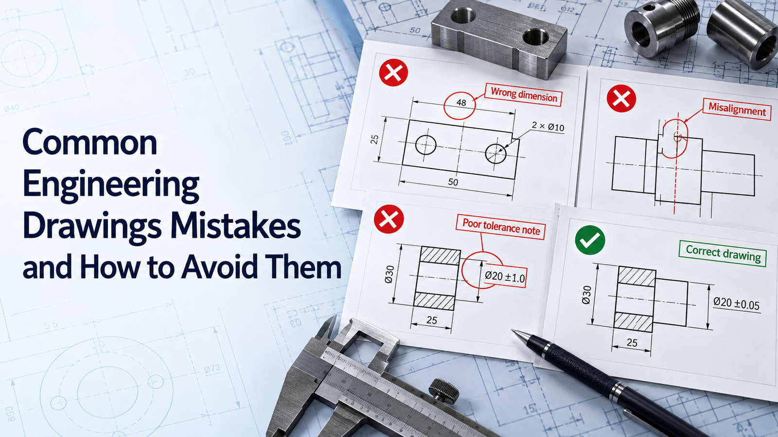
Engineering drawings are supposed to remove ambiguity.
When a drawing is incomplete, inconsistent, overcomplicated, or poorly controlled, it can create machining errors, assembly problems, inspection disputes, rework, production delays, and even equipment failures.
This is why engineering drawings troubleshooting is an important skill for designers, manufacturing engineers, inspectors, and maintenance teams.
Many drawing problems are not caused by the CAD software. They come from poor communication of design intent.
This guide explains common engineering drawing mistakes, why they happen, and how to avoid them in practical design and manufacturing work.
Key Problems and Solutions
1. Mistake: Missing Functional Dimensions
A drawing may look complete but still omit the dimensions required to manufacture or inspect the part.
Common missing dimensions include:
- Hole location
- Bore depth
- Slot width
- Shaft shoulder position
- Overall thickness
- Center distance
If a machinist must guess or measure from the CAD image, the drawing is incomplete.
How to Avoid It
Review the drawing from the manufacturer's point of view.
Ask:
- Can every feature be produced?
- Can every critical feature be inspected?
- Is any dimension implied rather than defined?
Every functional feature should have enough information to manufacture it correctly.
2. Mistake: Over-Dimensioning the Drawing
Adding too many dimensions can create conflicts.
For example, if a feature is dimensioned from multiple directions, accumulated tolerances may contradict each other.
This can make inspection difficult because two dimensions may both appear required even though they cannot always be satisfied simultaneously.
How to Avoid It
Dimension each feature using the minimum information needed to define it.
Avoid duplicate dimensions unless they are clearly marked as reference information.
3. Mistake: Poor Datum Selection
Datums should represent how the part is located, assembled, or inspected.
Poor datum selection can create:
- Difficult machining
- Poor alignment
- Inspection problems
- Assembly variation
For example, dimensioning critical holes from an unfinished outer edge may be unreliable if the part is actually assembled from a machined mounting face.
How to Avoid It
Choose functional reference surfaces.
Typical datums include:
- Mounting faces
- Bearing bores
- Locating edges
- Shaft axes
- Dowel holes
The drawing should match how the part works in the final machine.
4. Mistake: Excessive Chain Dimensioning
Chain dimensions can create tolerance accumulation.
For example:
- A
- B
- C
- D
If each dimension has variation, the final feature position may move significantly.
This can cause assembly problems even if every individual dimension is technically within tolerance.
How to Avoid It
Use baseline or datum-based dimensioning when multiple features must maintain position from a common reference.
This is especially useful for:
- Hole patterns
- Linear guide mounting holes
- Bearing supports
- Fixture locations
5. Mistake: Applying Tight Tolerances Everywhere
Tighter tolerances increase manufacturing difficulty and cost.
They may require:
- Slower machining
- Better machine tools
- More inspection
- Higher rejection rates
ISO 129-1:2018 provides general principles for presenting dimensions and associated tolerances.
How to Avoid It
Apply tight tolerances only where they affect function.
Examples include:
- Bearing fits
- Shaft diameters
- Guide mounting surfaces
- Locating features
Use wider general tolerances for noncritical dimensions.
6. Mistake: Using Tolerances Without Considering Process Capability
A tolerance may look reasonable in CAD but be difficult for the intended manufacturing process.
For example:
- Laser-cut plates
- Welded frames
- Precision grinding
- CNC machining
have very different achievable accuracy.
How to Avoid It
Match tolerance to the manufacturing method.
Discuss critical tolerances with manufacturing teams or suppliers before release.
7. Mistake: Using GD&T Without Understanding Function
Geometric tolerancing is powerful, but incorrect use can make drawings harder to manufacture and inspect.
Common issues include:
- Unnecessary position tolerances
- Incorrect datum order
- Overly tight flatness
- Redundant controls
- Confusing feature control frames
ISO 1101:2017 defines the ISO language for geometrical tolerancing.
How to Avoid It
Use GD&T only when it clearly communicates a functional geometric requirement.
Before adding a control, ask:
- What failure does it prevent?
- What datum should control it?
- How will it be inspected?
8. Mistake: Missing Section Views
Internal features may be difficult to understand using hidden lines alone.
Examples include:
- Bearing seats
- Counterbores
- Internal shoulders
- Keyways
- Recesses
ISO 128-3:2022 provides conventions for views, sections, and cuts.
How to Avoid It
Use a section view when internal geometry is important for manufacturing or assembly.
A clear section often communicates more effectively than many hidden lines.
9. Mistake: Too Many Unnecessary Views
The opposite problem also occurs.
Too many views make a drawing crowded and difficult to read.
How to Avoid It
Use only the views required to fully define the component.
Add detail views only for areas that need enlarged clarification.
10. Mistake: Incorrect or Inconsistent Line Types
Visible lines, hidden lines, centerlines, and cutting-plane lines have different meanings.
Inconsistent use can create confusion.
ISO 128-2:2022 defines line conventions used in technical product documentation.
How to Avoid It
Use recognized line types consistently.
Avoid manually changing line styles only for visual appearance.
11. Mistake: Missing Material Information
A drawing that only says "steel" may not provide enough information.
Material grade can affect:
- Strength
- Hardness
- Machinability
- Corrosion resistance
- Welding
How to Avoid It
Specify the exact material grade where function requires it.
Also include applicable:
- Heat treatment
- Hardness
- Coating
- Surface treatment
12. Mistake: Over-Specifying Surface Finish
Very fine surface finish requirements can increase machining cost.
Not every surface needs grinding or fine finishing.
How to Avoid It
Specify surface finish only where it affects:
- Bearing seating
- Sealing
- Sliding
- Wear
- Precision mounting
13. Mistake: Unclear Hole Callouts
Hole specifications can become confusing when information is incomplete.
Common problems include missing:
- Diameter
- Depth
- Thread specification
- Counterbore
- Countersink
- Quantity
How to Avoid It
Use complete hole callouts.
Group identical holes where appropriate.
14. Mistake: BOM and Drawing Do Not Match
An assembly drawing may call out item numbers that do not match the Bill of Materials.
This can result in:
- Wrong components
- Missing parts
- Procurement errors
How to Avoid It
Before release, compare:
- Item balloons
- Part numbers
- Quantities
- Descriptions
The drawing and BOM should always be synchronized.
15. Mistake: Using Wrong Fastener Lengths in Drawings
Fasteners may protrude too far, bottom out, or provide insufficient thread engagement.
How to Avoid It
Check:
- Grip length
- Thread engagement
- Washer thickness
- Nut position
- Clearance behind the hole
Fasteners should be modeled and reviewed as functional parts of the assembly.
16. Mistake: Ignoring Assembly Sequence
A part may be dimensionally correct but impossible to assemble.
Common problems include:
- Bolts inaccessible after another part is installed
- Bearings trapped between structures
- Motors impossible to remove
How to Avoid It
Review the assembly sequence using the 3D model and assembly drawing.
Ask how each component will be:
- Installed
- Tightened
- Aligned
- Removed
17. Mistake: Drawing Does Not Match the CAD Model
This is a serious document-control problem.
Possible mismatches include:
- Different hole sizes
- Old dimensions
- Wrong part number
- Different revision
How to Avoid It
Before release, compare the drawing against the final approved model.
Organizations should define which controlled source governs production.
18. Mistake: Weak Revision Control
Using the wrong revision can lead to expensive rework.
A controlled drawing should clearly show:
- Revision
- Date
- Change description
- Approval
How to Avoid It
Remove obsolete drawings from active production systems.
Make sure suppliers and internal teams receive the latest approved revision.
19. Mistake: Drawings Are Difficult to Inspect
A drawing may specify requirements that are difficult or impossible to measure.
Examples include:
- Inaccessible datums
- Extremely tight internal dimensions
- Complex GD&T without available inspection equipment
How to Avoid It
Design drawings with inspection in mind.
Ask:
- How will this feature be measured?
- Is the datum accessible?
- Is the required instrument available?
20. Mistake: Installation Drawings Lack Site Information
Installation drawings may omit:
- Anchor locations
- Orientation
- Overall dimensions
- Service clearances
- Utility connection points
This can cause site modification or delayed commissioning.
How to Avoid It
Create a dedicated installation drawing with the information the installation team actually needs.
Engineering Drawing Troubleshooting Checklist
| Drawing Problem | Recommended Fix |
|---|---|
| Missing dimensions | Add functional manufacturing dimensions |
| Duplicate dimensions | Remove redundant controls |
| Poor datum | Use functional reference surfaces |
| Tolerance stack-up | Use baseline dimensioning |
| Excessive tolerance | Match tolerance to function |
| Incorrect GD&T | Relate controls to design intent |
| Hidden geometry unclear | Add section view |
| Material unclear | Specify grade |
| BOM mismatch | Synchronize items |
| Wrong revision | Strengthen document control |
| Difficult inspection | Review measurement method |
| Poor installation data | Add site interface dimensions |
A Practical Drawing Review Process
Before releasing a drawing, review it in five passes.
Pass 1: Geometry
Check that all features are shown clearly.
Pass 2: Dimensions
Confirm every functional feature is defined.
Pass 3: Tolerances and GD&T
Check that tolerances match the actual function and manufacturing capability.
Pass 4: Manufacturing and Inspection
Confirm that the part can be produced and measured.
Pass 5: Documentation
Verify:
- Part number
- Revision
- Material
- Notes
- BOM
- CAD model
This simple process can prevent many drawing-related errors.
Conclusion
Good engineering drawings troubleshooting focuses on clarity, function, manufacturability, inspection, and document control.
Common problems such as missing dimensions, poor datum selection, excessive tolerances, incorrect GD&T, unclear section views, BOM mismatches, and outdated revisions can lead directly to manufacturing errors and project delays.
Standards such as ISO 128-1, ISO 128-2, ISO 128-3, ISO 129-1, and ISO 1101 provide a consistent framework for technical drawing communication.
The best engineering drawing is not the one with the most dimensions or symbols.
It is the one that clearly communicates exactly what is required to manufacture, inspect, assemble, and install the product correctly.