
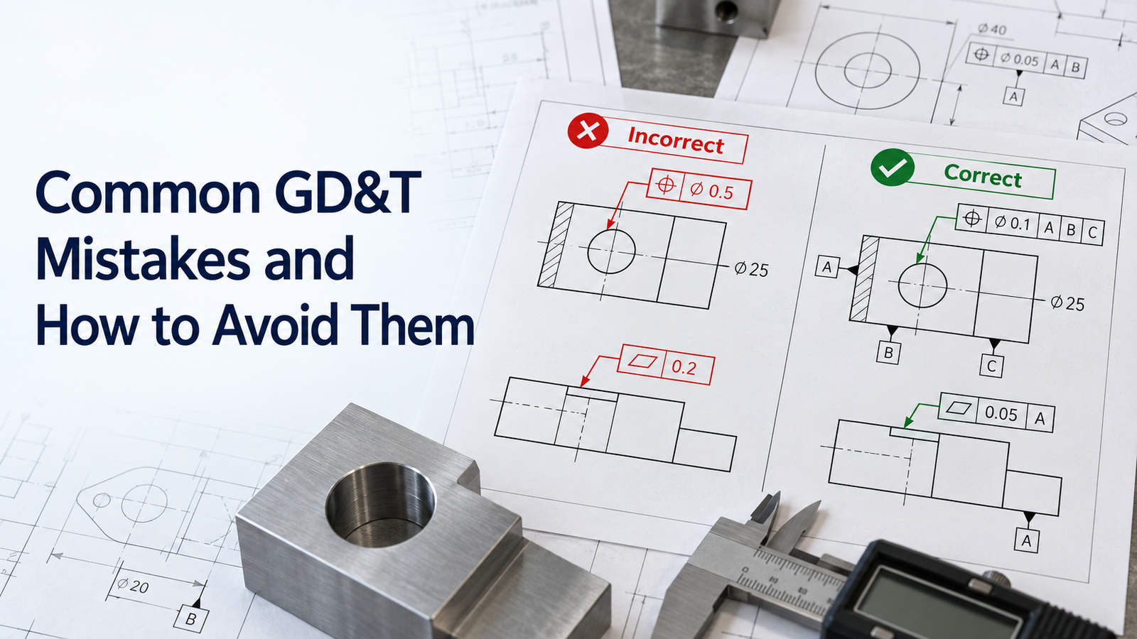
Geometric Dimensioning and Tolerancing, or GD&T, is designed to make engineering requirements clearer. However, when it is applied incorrectly, it can create the opposite result.
Poorly selected datums, unnecessary controls, incorrect modifiers, excessive tolerance tightness, and inspection requirements that are difficult to verify can create manufacturing confusion, higher cost, rejected parts, assembly issues, and repeated drawing revisions.
This is why geometric dimensioning and tolerancing troubleshooting is an important skill for designers, manufacturing engineers, quality teams, and suppliers.
ISO 1101:2017 remains the current published ISO standard for geometrical tolerancing, while ASME Y14.5-2018 (R2024) remains in effect and is widely used for GD&T practice.
This guide explains common GD&T mistakes, why they happen, and how to avoid them in practical engineering work.
Key Problems and Solutions
1. Mistake: Using GD&T Without Understanding Function
The biggest GD&T mistake is adding symbols simply because they look technically advanced.
Every geometric control should solve a functional problem.
Before adding a tolerance, ask:
- What feature relationship matters?
- What failure am I trying to prevent?
- What datum should control this feature?
- How will the requirement be inspected?
For example, adding perpendicularity to a surface has little value if that surface does not affect assembly or function.
How to Avoid It
Start with design intent.
Use GD&T only where it improves communication of form, orientation, location, or runout.
2. Mistake: Choosing the Wrong Primary Datum
The primary datum establishes the first reference for the datum reference frame.
If it does not represent how the part is mounted or functions, the entire tolerance scheme may become difficult to manufacture and inspect.
Common poor choices include:
- Decorative outer surfaces
- Unstable cast surfaces
- Nonfunctional edges
How to Avoid It
Select a datum feature that provides a stable and functional reference.
Typical primary datums include:
- Mounting faces
- Precision base surfaces
- Functional interfaces
The datum structure should reflect how the component is assembled and used.
3. Mistake: Incorrect Datum Order
Datum sequence matters.
A feature control frame referencing A-B-C does not mean the same thing as A-C-B.
Datum order establishes the degrees of freedom constrained by the datum reference frame.
How to Avoid It
Think about how the part should be located:
- Primary datum establishes the main orientation.
- Secondary datum constrains additional movement.
- Tertiary datum completes location.
Use the same logic as the actual functional setup.
4. Mistake: Over-Tolerancing the Part
One of the most common cost problems is applying very tight geometric tolerances everywhere.
This can increase:
- Machining time
- Inspection time
- Scrap risk
- Supplier price
GD&T should improve functional control, not make every feature extremely precise.
How to Avoid It
Set tolerances based on functional need.
A precision bearing interface may need close control.
A noncritical cover bracket may not.
5. Mistake: Adding Redundant Controls
Sometimes a drawing controls the same geometric condition more than once.
For example, a surface may have:
- Flatness
- Parallelism
- Profile
even though one properly defined control already provides the required function.
Redundant requirements can confuse suppliers and inspectors.
How to Avoid It
Review each control and ask whether another requirement already controls that characteristic.
Remove unnecessary duplication.
6. Mistake: Using Position Tolerance Incorrectly
Position is one of the most widely used GD&T controls.
It is commonly used for:
- Holes
- Pins
- Bores
- Feature patterns
Common mistakes include:
- Wrong datum references
- Missing basic dimensions
- Excessively tight tolerance
- Incorrect material-condition modifier
How to Avoid It
Make sure the feature's theoretically exact location is defined by basic dimensions and that the datum reference frame matches the functional assembly.
7. Mistake: Forgetting Basic Dimensions
Position and profile tolerances often depend on basic dimensions.
Basic dimensions define theoretically exact geometry.
Without them, the intended feature location or profile may be unclear.
How to Avoid It
Check that all controlled geometry has the basic dimensions needed to establish its nominal location, orientation, or shape.
8. Mistake: Confusing MMC and LMC
Maximum Material Condition (MMC) and Least Material Condition (LMC) modifiers can be powerful, but they are often misunderstood.
For a hole:
- MMC is the smallest allowed hole size.
- LMC is the largest allowed hole size.
For an external feature such as a pin:
- MMC is the largest allowed size.
- LMC is the smallest allowed size.
Misunderstanding this can lead to incorrect bonus tolerance calculations.
How to Avoid It
Always think in terms of material amount rather than simply largest or smallest numerical size.
Use MMC or LMC only when the functional requirement benefits from it.
9. Mistake: Assuming MMC Is Always Better
MMC can support functional gauging and bonus tolerance, but it is not appropriate for every feature.
Some features must maintain geometric accuracy regardless of size.
How to Avoid It
Use MMC when size and geometric tolerance interact functionally, such as in many clearance-hole or pin assemblies.
Do not add it automatically.
10. Mistake: Misusing Runout
Runout controls are often applied to rotating components.
Common mistakes include:
- Using circular runout when total runout is needed
- Referencing the wrong datum axis
- Applying runout where another control is clearer
How to Avoid It
Use circular runout when controlling individual circular sections during rotation.
Use total runout when controlling the complete surface along its length.
Make sure the datum establishes the actual functional rotational axis.
11. Mistake: Using Flatness When Orientation Is the Real Requirement
Flatness controls only the form of a surface.
It does not control its orientation relative to another feature.
A surface can be very flat but still be tilted.
How to Avoid It
If the function requires orientation relative to a datum, use an appropriate orientation control such as:
- Parallelism
- Perpendicularity
- Angularity
Use flatness only when the surface itself must be flat independent of a datum.
12. Mistake: Using Parallelism Without a Functional Datum
Parallelism requires a reference.
If the selected datum does not represent the actual assembly reference, the control may not protect function.
How to Avoid It
Reference the surface or axis that defines the real working relationship.
For example, a guide mounting face may need to be parallel to the machine base datum.
13. Mistake: Using Profile Without Understanding What It Controls
Profile is a flexible GD&T control.
It can control complex surfaces and may affect:
- Form
- Orientation
- Location
depending on how it is specified.
Because of this flexibility, profile is sometimes applied without a clear understanding of what is being constrained.
How to Avoid It
Define the basic geometry clearly and choose datum references deliberately.
Do not use profile simply to replace all other controls unless that actually represents the intended function.
14. Mistake: Datum Features Are Too Small or Unstable
A datum feature must establish a repeatable reference.
If the selected surface is very small, rough, flexible, or unstable, inspection results may vary.
How to Avoid It
Choose datum features that create a stable setup and are representative of how the part functions.
15. Mistake: Ignoring Inspection Capability
A tolerance may be theoretically correct but extremely difficult to inspect.
This can increase cost or create disagreement between supplier and customer.
NIST has highlighted the importance of correct implementation and interpretation of GD&T in CAD and downstream inspection systems.
How to Avoid It
Before release, ask:
- Can the requirement be measured?
- Is a CMM required?
- Is the datum accessible?
- Does the supplier have the required equipment?
Design and inspection planning should be connected.
16. Mistake: Different Teams Interpret the Same GD&T Differently
Complex GD&T can be interpreted differently by:
- Design
- Manufacturing
- Quality
- Suppliers
This is especially common when company practices mix ISO GPS and ASME Y14.5 conventions without clarity.
How to Avoid It
Define which standard governs the drawing.
Do not mix notation conventions casually.
Train teams on the standard actually used by the organization.
17. Mistake: Mixing ISO and ASME Rules Without Control
ISO 1101 and ASME Y14.5 are both major GD&T frameworks.
They share many concepts but are not identical in every rule, symbol interpretation, and default.
How to Avoid It
State the governing standard on the drawing or in company drafting standards.
Avoid assuming every symbol is interpreted identically under both systems.
18. Mistake: CAD Annotation Looks Correct but Semantic Data Is Wrong
Modern CAD systems can store GD&T as structured product data.
NIST testing has shown that CAD implementations can contain errors in semantic representation or graphical presentation of GD&T.
How to Avoid It
For model-based workflows:
- Validate PMI
- Check exported data
- Review downstream interpretation
- Confirm inspection software reads the requirement correctly
Do not rely only on what the annotation looks like on screen.
19. Mistake: Failing to Review Tolerance Stack-Up
GD&T does not eliminate tolerance accumulation automatically.
Assemblies may still suffer from combined variation across:
- Multiple parts
- Datum transfers
- Fits
- Spacer stacks
How to Avoid It
Perform tolerance-stack analysis for critical assembly relationships.
Check the complete functional chain, not only individual part tolerances.
20. Mistake: Using GD&T to Fix a Poor Mechanical Design
GD&T cannot compensate for a fundamentally poor design.
For example, if a structure is too flexible or a bearing arrangement is incorrect, adding tighter tolerances may only increase cost.
How to Avoid It
Solve mechanical design problems first.
Then use GD&T to communicate the geometry required to make the design work.
21. Mistake: Missing Revision Control After GD&T Changes
A change to:
- Datum structure
- Position tolerance
- Profile
- Runout
can significantly affect manufacturing and inspection.
If old drawings remain in circulation, different suppliers may produce different versions.
How to Avoid It
Use controlled revisions and clearly communicate tolerance changes to:
- Suppliers
- Production
- Quality
- Maintenance
Practical GD&T Troubleshooting Checklist
| Problem | Check First |
|---|---|
| Part fits poorly | Position, datum scheme and size |
| Bearing failure | Runout, perpendicularity and alignment |
| Hole pattern mismatch | Position and basic dimensions |
| Surface rocks during assembly | Flatness |
| Guide binding | Parallelism and datum selection |
| CMM rejects supplier part | Standard interpretation and setup |
| Part expensive to manufacture | Overly tight or redundant tolerances |
| Different inspection results | Datum simulation and measurement method |
| Replacement part does not fit | MMC/LMC and interchangeability requirements |
| CAD and inspection disagree | Semantic PMI and software interpretation |
A Better GD&T Review Process
Before releasing a GD&T drawing, review it in five stages.
Stage 1: Function
Identify which feature relationships truly matter.
Stage 2: Datums
Confirm that the datum reference frame matches how the part functions.
Stage 3: Controls
Use the simplest geometric controls that communicate the requirement.
Stage 4: Manufacturing and Inspection
Confirm the tolerance is practical to make and verify.
Stage 5: Documentation
Check the governing standard, revision, basic dimensions, modifiers, and notes.
This structured review can prevent many GD&T-related manufacturing problems.
Conclusion
Good geometric dimensioning and tolerancing troubleshooting starts with understanding design intent.
Common GD&T mistakes include poor datum selection, incorrect datum order, excessive tolerance tightness, redundant controls, position errors, MMC/LMC confusion, runout misuse, inspection difficulty, and inconsistent standard interpretation.
ISO 1101:2017 remains the current published ISO standard for geometrical tolerancing, while ASME Y14.5-2018 (R2024) remains in effect for dimensioning and tolerancing practice.
NIST research also shows why correct digital representation and downstream interpretation of GD&T matter in modern CAD-based workflows.
The best GD&T scheme is not the one with the most symbols.
It is the one that communicates functional requirements clearly, can be manufactured and inspected realistically, and supports reliable interchangeability and assembly.